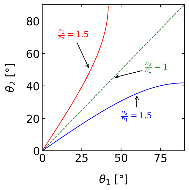
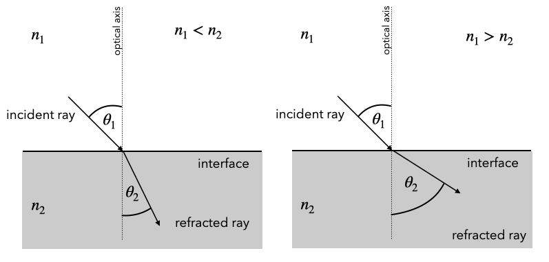
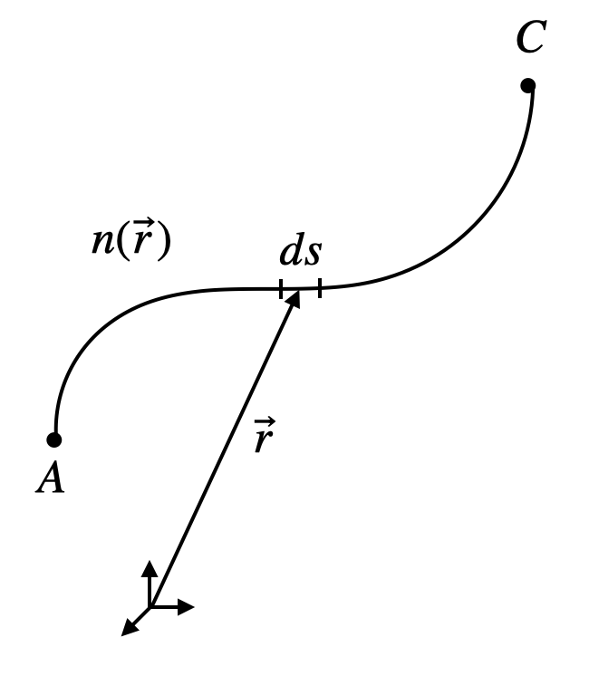
The law of refraction is the second important law of geometrical optics. It relates the refractive index and angle of incidence on one side of an interface to the refractive index and angle of refraction on the other side. Both the law of reflection and the law of refraction can be derived from more fundamental principles such as Fermat’s principle of least time and are consistent with the conservation of energy. Their relation to momentum is more complex and involves considering the interaction of light with the medium at an atomic level. These laws provide a mathematical framework for predicting how light behaves when it encounters interfaces between different media, forming the basis for understanding a wide range of optical phenomena and the design of optical devices.
Total Internal Reflection
The above diagram reveals a special case occurring when . Under these conditions, we can increase the incident angle until the outgoing angle reaches . At this point, the refracted ray would be traveling along the interface between the two media. For any incident angle larger than this critical angle, there is no refracted ray at all; instead, we observe only a reflected ray. This phenomenon, known as total internal reflection, occurs despite the fact that the material with refractive index is completely transparent.
Let’s formalize this concept mathematically. Using Snell’s law and setting , we obtain the equation for the critical angle :
Note that the function requires an argument , which is why this phenomenon only occurs when .
It’s important to understand that during total internal reflection, all of the light energy is reflected back into the first medium, hence the term ‘total’. However, electromagnetic optics reveals an interesting subtlety: an evanescent wave penetrates a short distance into the second medium, though it doesn’t propagate energy across the boundary.
When the incident angle exceeds the critical angle, Snell’s law as we’ve written it no longer applies. Instead, we observe perfect reflection, where the angle of reflection equals the angle of incidence, just as in regular reflection from a mirror. This reflection occurs without any loss of energy to the second medium, making it an extremely efficient process.
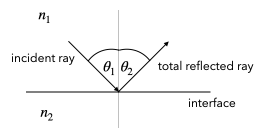
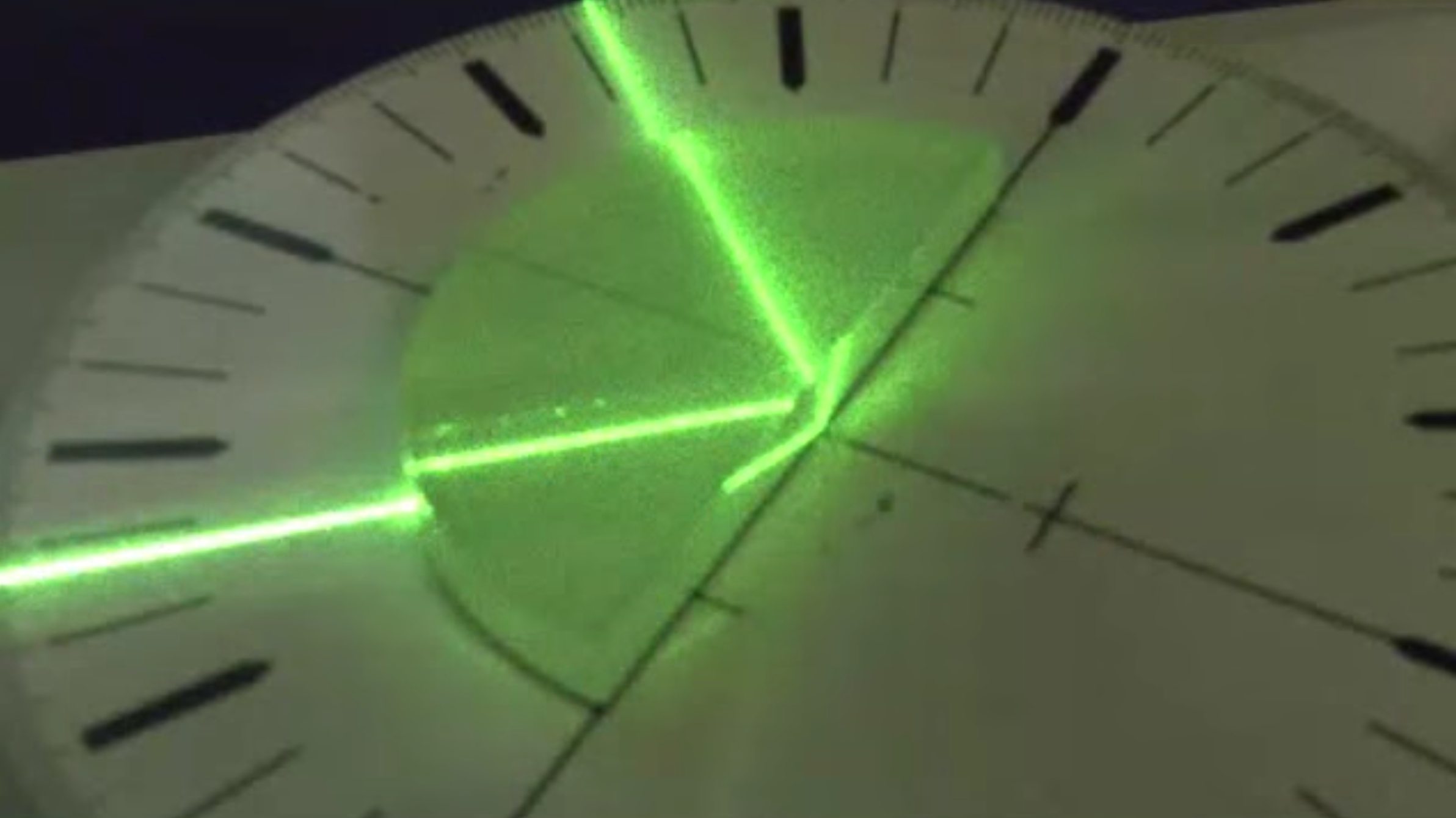
Total internal reflection occurs when light is passing from higher refractive index to lower refractive index materials for incidence angle larger than a critical angle
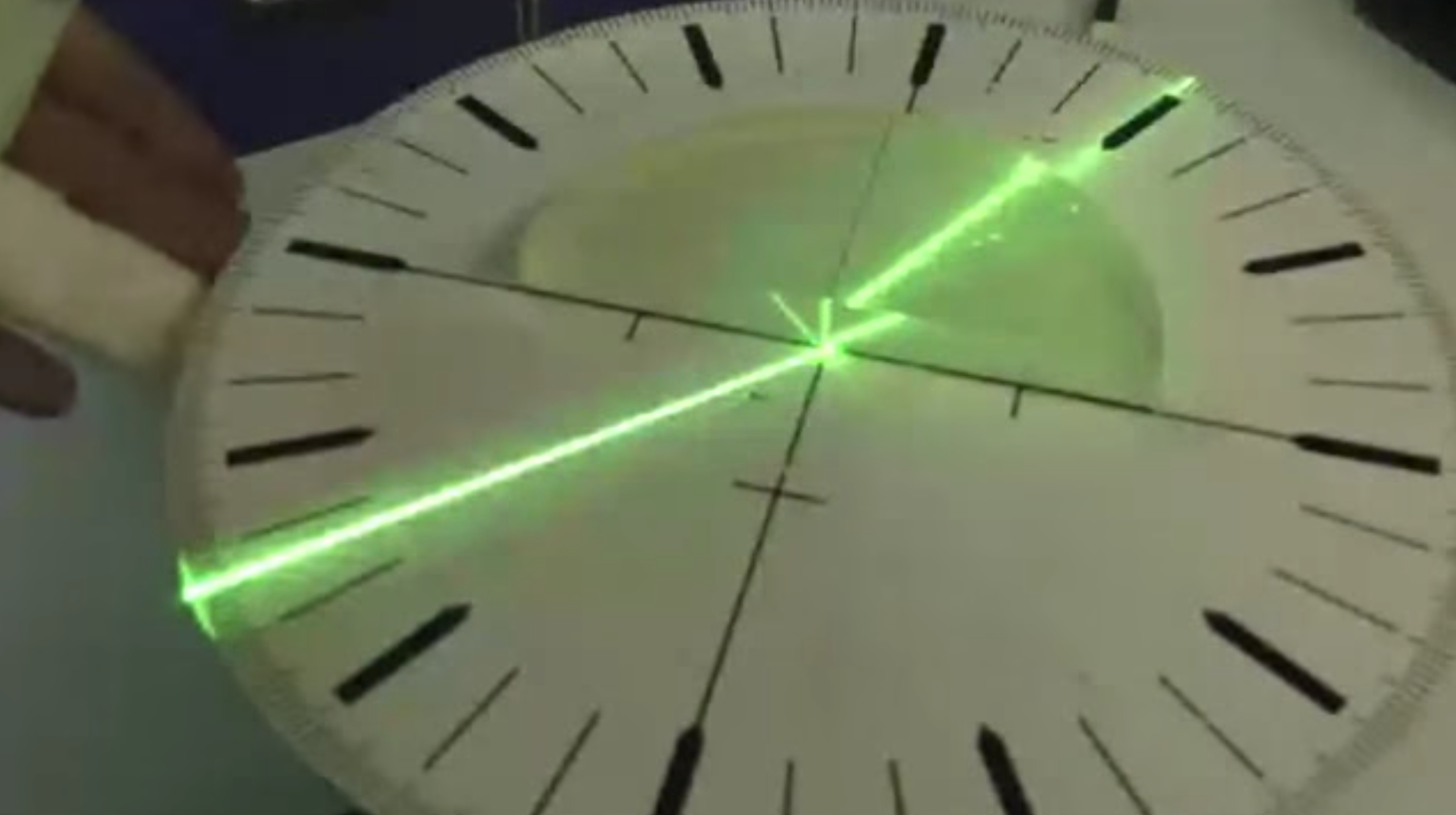
We can demonstrate total internal reflection very easily with a water basin, for example, where we couple in light from a laser from the side.

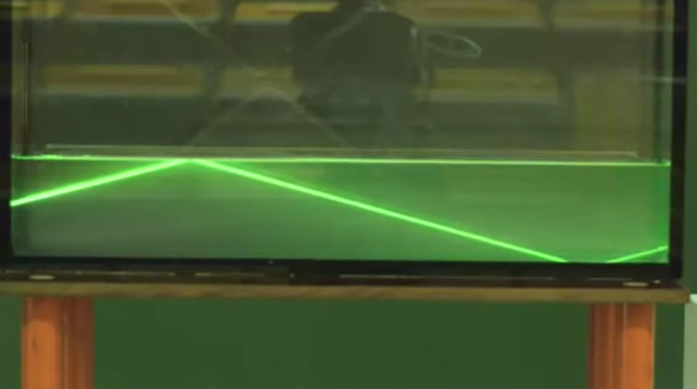
But you could try that yourself also in the bath tub diving below the water surface.
Total internal reflection has numerous practical applications:
- Fiber optic communications: Light signals can travel long distances with minimal loss through optical fibers.
- Optical instruments: Prisms in binoculars and telescopes use total internal reflection to manipulate light paths.
- Gemstones: The sparkle of diamonds is enhanced by total internal reflection trapping light within the stone.
- Medical endoscopes: Total internal reflection helps guide light through flexible tubes for internal imaging.
Optical Fibers and Total Internal Reflection
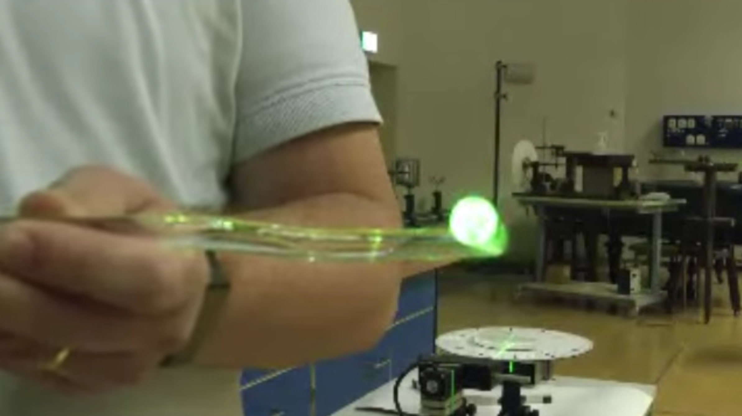
Total internal reflection plays a crucial role in modern telecommunications, particularly in optical fibers, which are also part of many experimental setups. These fibers are essentially ultra-thin glass wires, ranging in diameter from a few micrometers to several hundred micrometers, designed to transport light over long distances with minimal loss.
The structure of an optical fiber is key to its function:
- Core: A central glass core with a refractive index
- Cladding: A surrounding layer with a slightly lower refractive index
This difference in refractive indices is what allows total internal reflection to occur within the fiber.
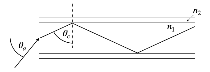
For light to propagate effectively through the fiber, it must enter at an angle that ensures total internal reflection at the core-cladding interface. This leads to the concept of the acceptance angle, , which is the maximum angle at which light can enter the fiber and still undergo total internal reflection.
To characterize this acceptance angle, optical engineers use a parameter called the Numerical Aperture (NA).
The Numerical Aperture of a fiber is defined as the sine of the maximum acceptance angle:
This equation relates the NA directly to the refractive indices of the core and cladding. The derivation of this formula involves applying Snell’s law at the air-fiber interface and at the core-cladding interface, then using the condition for total internal reflection.
In practice, typical values for the refractive indices might be for the core and for the cladding. Plugging these into our equation:
This means that light entering the fiber within a cone of about 11.5° (arcsin(0.2)) from the fiber’s axis will be transmitted through the fiber via total internal reflection.
The NA is an important parameter in fiber optic design:
- It determines the light-gathering ability of the fiber.
- It affects the fiber’s bandwidth and its susceptibility to certain types of signal distortion.
- It influences how easily the fiber can be coupled to light sources and other fibers.
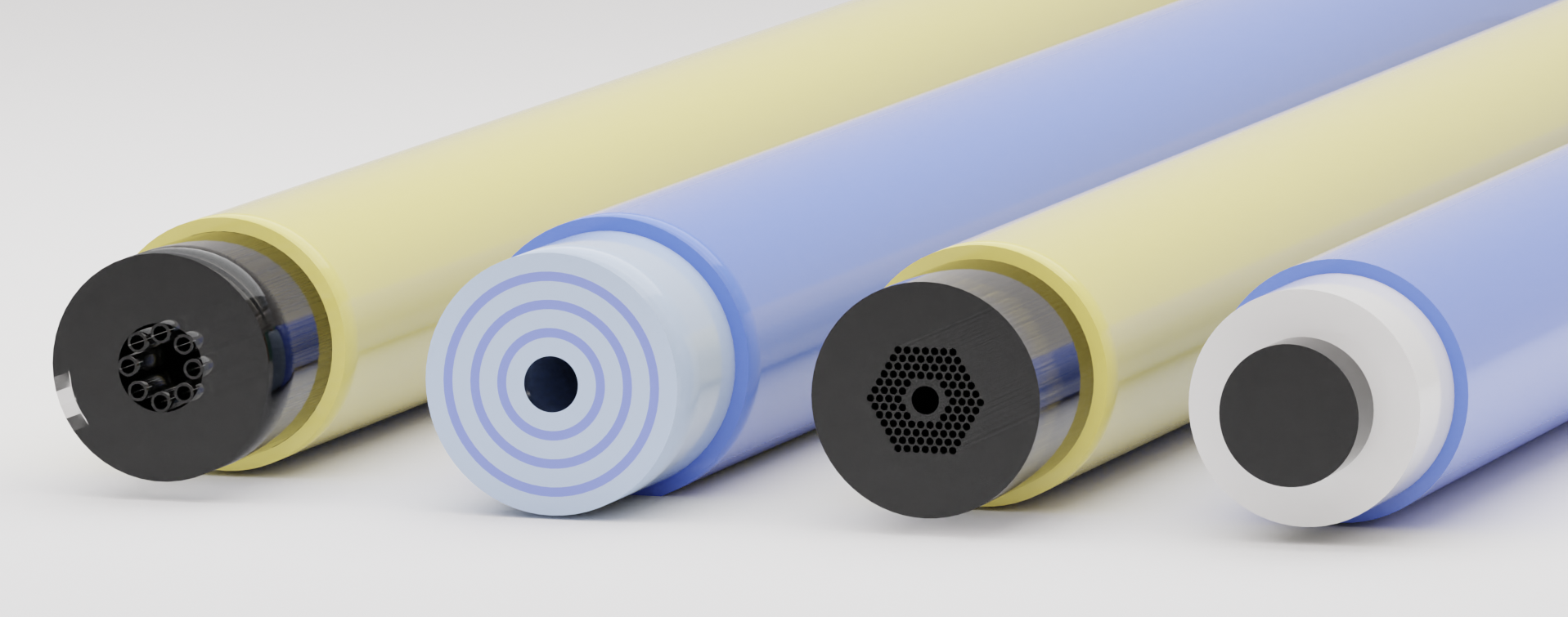
Optical fibers come in various types, each optimized for different applications. Some fibers are designed to transmit light over long distances with minimal loss, while others are engineered for specific wavelengths or to guide light in unusual ways. The figure below shows a few examples of optical fiber types.
