The Wave Character of Particles

Electron diffraction and de Broglie wavelength

De Broglie proposed that if electromagnetic waves could exhibit particle-like properties, perhaps particles could demonstrate wave-like behavior. To explore this concept and determine a particle’s wavelength, he merged principles from classical mechanics with the quantum model of light. Consider a particle with mass \(m\) moving at velocity \(v\); its momentum \(p\) is expressed as

\[ p = m \cdot v \mathrm{.} \]

The quantum model of light shows us that a photon’s momentum can be written as

\[ p = \hbar \cdot k = \frac{h}{\lambda} \]

By combining these equations and assuming the momentum descriptions are equivalent, we can derive the wavelength for a particle:

\[ \lambda = \frac{h}{p} = \frac{h}{\sqrt{2 m E_{\mathrm{kin}}}} \mathrm{.} \]

De Broglie first published this relationship in his 1924 PhD thesis, and the particle wavelength calculated using this equation became known as the de Broglie wavelength. This revolutionary proposal suggested that the wave-particle duality observed in light might be a universal principle applying to all matter.

The basis for measurements veryfying the wave character of particles is the acceleration of charged particles. This was enabled by the development of vacumm technolgy and the invention of the electron gun by J.J. Thomson in 1897. The electron gun is a device that accelerates electrons to high speeds and directs them onto a target. The electrons are accelerated by an electric field, which is generated by a voltage difference between the cathode and the anode of the electron gun. The kinetic energy of the electrons is given by the voltage difference between the cathode and the anode. The electrons are then directed onto a target, where they can be reflected or diffracted. The reflection or diffraction of the electrons can be observed by a detector, which is placed behind the target.

Figure 1— Electron tube developed by J.J. Thomson. The electrons are emitted from a heated cathode and accelerated by a voltage between the cathode and anode.

Modern accelerators can accelerators for charged particles can either be very large, such as the well known LHC at CERN, or very small an fit on a silicon chip as displayed in the image below.
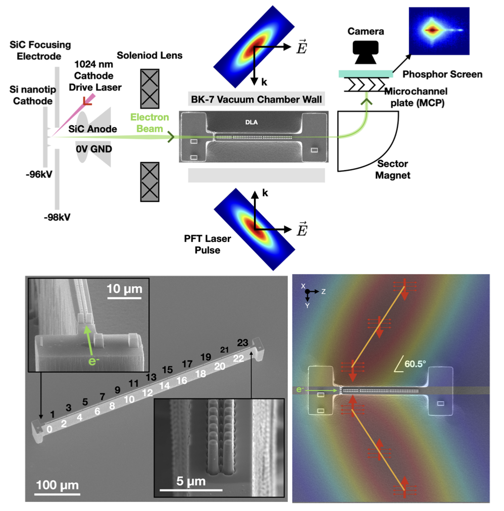
Figure 2— Top: accelerator system overview. Bottom left: DLA100 476 μm on a 500 μm long mesa. Cells labeled as black are longitudinally focusing and transversely defocusing, while white are longitudinally defocusing and transversely focusing. Bottom right: DLA100 46 μm powered by two 60.5 0.7° incident PFT laser pulses. The orange line shows the electron- laser overlap on the laser pulse as it travels through the structure.(from Broaddus et al. 2024)

Experiment by Davisson and Germer

In 1926, Davisson and Germer provided experimental proof of de Broglie’s hypothesis of matter waves by observing electron diffraction through crystalline material. In their experiment, electrons were accelerated by a voltage \(U\), giving them kinetic energy \(E_{\mathrm{kin}} = e \cdot U\). According to de Broglie’s relation, these electrons would have a wavelength of

\[\lambda = \frac{h}{\sqrt{2 m e U}}\]

where \(h\) is Planck’s constant, \(m\) is the electron mass, and \(e\) is the elementary charge.

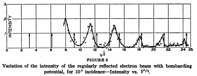
Their key experiment involved reflecting electrons from a nickel crystal. The results are shown in the following figures:
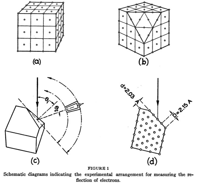
Figure 3— Sketch of an experiment by Davisson and Germer. The electrons are accelerated by a voltage \(U\) and directed onto a nickel crystal. The diffraction pattern is recorded on a fluorescent screen. The diameter of the diffraction rings decreases with increasing accelerating voltage.
Figure 4— Distribution-in-angle of electrons of all speeds issuing from a [111] face of a nickel crystal for various angles of incidence and speeds of bombardment.
Figure 5— Variation of the intensity of the regularly reflected electron beam with bombarding potential, for 10° incidence-Intensity vs. \(V^{1/2}\).

The wavelength of the electrons depends inversely on the square root of the accelerating voltage. When waves reflect on a crystal lattice, the reflection from different lattice planes can interfere constructively or destructively depending on the wavelength and angle of incidence. The sine of the reflection angle \(\theta\) with constructive interference follows Bragg’s law:

\[ 2d\sin \theta = n \cdot \lambda \tag{Bragg's law} \]

where \(n\) is the order of the maximum and \(d\) is the distance between lattice planes. For the [111] face of the nickel crystal used, \(d = \frac{a}{\sqrt{3}}\), where \(a = 0.352 \;\mathrm{nm}\) is the lattice constant, giving \(d = 0.203 \;\mathrm{nm}\).

Angle in Bragg’s law

Note that the angle \(\theta\) in Bragg’s law is the angle between the incident electron beam and the lattice plane. The angle of reflection \(\theta\) is thus twice the angle between the incident electron beam and the lattice plane. This is in contrast to optics and the drawing of Davisson and Germer, where the angle of reflection \(\theta\) is the angle between the incident electron beam and the normal of the lattice plane.

Combining the voltage dependence of wavelength with Bragg’s law:

\[ \sin(\theta) = \frac{h}{\sqrt{2 m e U}} \cdot \frac{n}{2 d} \]

Solving for the voltage giving constructive interference at angle \(\theta\):

\[ \sqrt{U} = \frac{h}{\sqrt{2 m e}} \cdot \frac{n}{2 d \sin(\theta)} = n a \]

where \(a= \frac{h}{\sqrt{2 m e}} \cdot \frac{1}{2 d \sin(\theta)}\) is constant. This predicts a linear relationship between reflection maxima and square root of accelerating voltage, matching experimental results and confirming the wave nature of electrons as described by de Broglie.

Atomic and molecular diffraction

Since then many other experiments have been carried out, which show the diffractive behavior of particles. Below are some examples of such experiments.

Atomic diffraction

Below is an example of atomic diffraction by the group of Toennies in Göttingen from 2000. In this experiment Helium atoms were directed onto a nanofabricated grating.
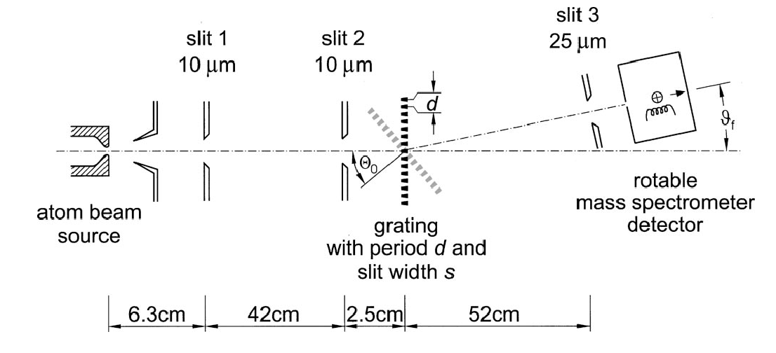
Figure 6— Schematic top view of the apparatus used in the He atom diffraction experiments. The diffraction grating has a period of 100 nm and can be rotated by an angle 0 about an axis perpendicular to the plane of the page. The gratings are 200 m wide and 5 mm high. (from Toennies et al.)

The results of this experiment are shown in the following figure.
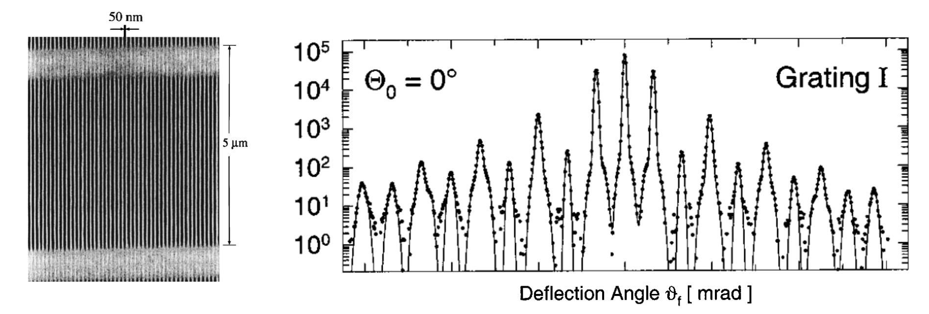
Figure 7— Electron micrograph of a small part of a grating. Diffraction spectra from grating I fitted by a sum of Gaussians. (from Toennies et al.)

Molecular diffraction

Experiments like that can even be extended to molecules. Below is an example for diffraction experiments in \(C_{60}\) molecules by the group of Zeilinger in Vienna from 1999. \(C_{60}\) are large molecules (buckyball molecules or Buckminsterfullerenes) consisting of 60 carbon atoms.
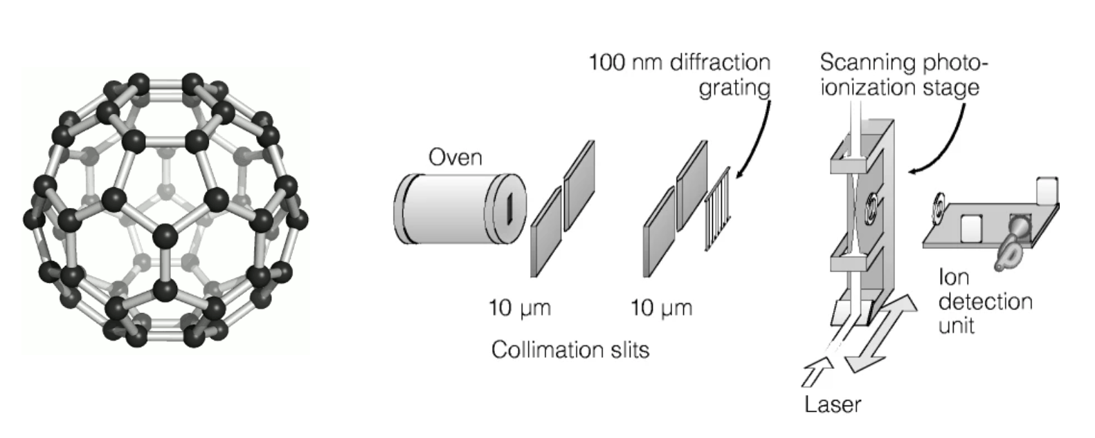
Figure 8— Schematic of the molecular beam apparatus. The \(C_{60}\) (structure on the left) molecules are produced in a resistively heated oven and are collimated by a skimmer. The molecules are then directed onto a nanofabricated grating. (from Zeilinger et al.)

The results of this experiment are shown in the following figure.
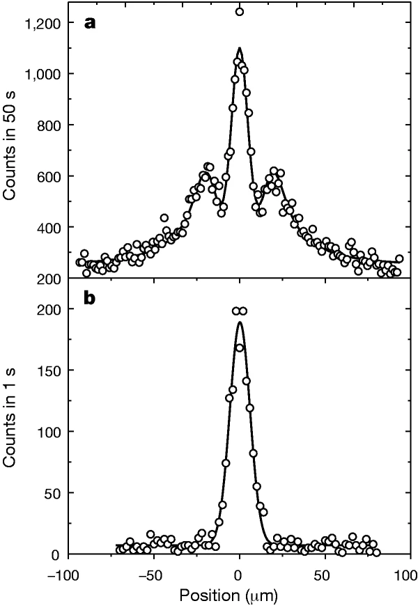
Figure 9— Experimental results showing the diffraction pattern of \(C_{60}\) molecules on the top and the a reference without \(C_{60}\) atoms on the bottom (from Zeilinger et al.)