Quantum Optics: From Classical Fields to Entangled Photons

Quantization of the Electromagnetic Field

Everything in this lecture rests on a single structural fact: one mode of the electromagnetic field is mathematically a harmonic oscillator. Once this is established, the entire machinery of the quantum harmonic oscillator, with its ladder operators, number states and zero-point energy, applies verbatim to light. This section derives the correspondence directly from the electric and magnetic fields of a single cavity mode and then quantizes it.

One Mode of the Field

Consider the simplest situation: an ideal cavity formed by two perfect mirrors at \(z = 0\) and \(z = L\), with the field polarized along \(x\). The boundary conditions select standing waves with wavenumber \(k = m\pi/L\) and frequency \(\omega = ck\). We pick one of these modes and put all its time dependence into an amplitude \(q(t)\):

\[E_x(z,t) = \mathcal{E}_0\, q(t)\, \sin(kz) \tag{1}\]

The constant \(\mathcal{E}_0 = \sqrt{2\omega^2/(\varepsilon_0 V)}\), with \(V\) the mode volume, is a normalization chosen purely so that the results below take their simplest form. The name \(q\) is deliberate: this amplitude will turn out to play the role of the position of an oscillator.

The two curl equations of Maxwell now do two separate jobs. The Ampère-Maxwell law \(\nabla \times \mathbf{B} = \mu_0\varepsilon_0\, \partial_t \mathbf{E}\) fixes the magnetic field that must accompany this electric field,

\[B_y(z,t) = \frac{\mathcal{E}_0}{c^2 k}\, \dot{q}(t)\, \cos(kz), \tag{2}\]

so the magnetic amplitude is the time derivative \(\dot{q}\). Faraday’s law \(\nabla\times\mathbf{E} = -\partial_t \mathbf{B}\) then imposes a condition on \(q(t)\) itself:

\[\ddot{q} + \omega^2 q = 0 . \tag{3}\]

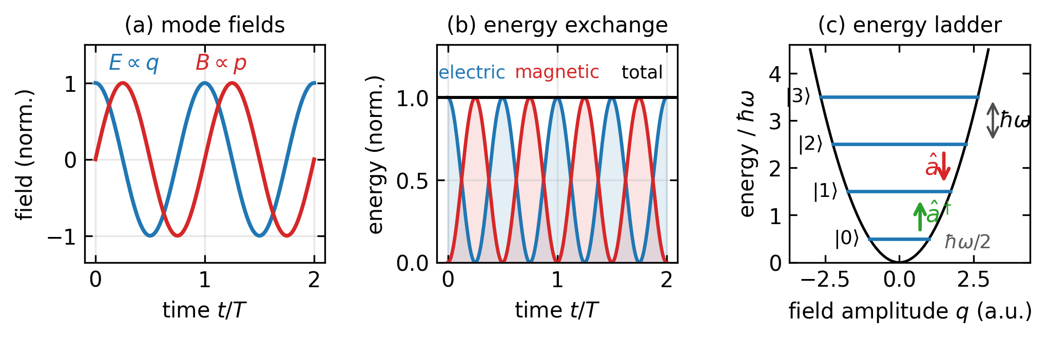
The mode amplitude obeys exactly the equation of motion of a harmonic oscillator of frequency \(\omega\). Note also the geometry contained in Equation 1 and Equation 2: where the electric field has antinodes the magnetic field has nodes, and the two oscillate \(90°\) out of phase in time.

The Field Energy Is an Oscillator Hamiltonian

The electromagnetic energy stored in the cavity is

\[H = \frac{1}{2}\int_V \left( \varepsilon_0 E_x^2 + \frac{B_y^2}{\mu_0} \right) dV .\]

Inserting Equation 1 and Equation 2 and using \(\int_V \sin^2(kz)\, dV = \int_V \cos^2(kz)\, dV = V/2\), all prefactors cancel by design of \(\mathcal{E}_0\) and we are left with

\[H = \frac{1}{2}\left(p^2 + \omega^2 q^2\right), \qquad p \equiv \dot{q} . \tag{4}\]

This is precisely the Hamiltonian of a mechanical harmonic oscillator of unit mass. The electric field energy plays the role of the potential energy \(\omega^2 q^2/2\) and the magnetic field energy plays the role of the kinetic energy \(p^2/2\). Hamilton’s equations \(\dot{q} = \partial H/\partial p\) and \(\dot{p} = -\partial H/\partial q\) reproduce Equation 3, which confirms that \(q\) and \(p\) are a legitimate pair of canonically conjugate variables.

It is worth pausing on what \(q\) and \(p\) actually are. They are not the position and momentum of any particle; there is no mass on a spring anywhere in the problem. They are the instantaneous amplitudes of the electric and the magnetic field of the mode. Light is an oscillation in field space, with the energy swinging back and forth between electric and magnetic form exactly as it swings between potential and kinetic energy in a pendulum (Figure 1).

Code
fig, axes = plt.subplots(1, 3, figsize=get_size(18, 6))

# (a) field oscillations, 90 degrees out of phase
t = np.linspace(0, 2, 500)   # time in units of the period T
ax = axes[0]
ax.plot(t, np.cos(2*np.pi*t), color='C0', lw=1.8)
ax.plot(t, np.sin(2*np.pi*t), color='C3', lw=1.8)
ax.text(0.35, 1.18, r'$E \propto q$', color='C0', fontsize=10, ha='center')
ax.text(1.15, 1.18, r'$B \propto p$', color='C3', fontsize=10, ha='center')
ax.set_xlabel('time $t/T$'); ax.set_ylabel('field (norm.)')
ax.set_ylim(-1.35, 1.5); ax.set_title('(a) mode fields', fontsize=10)
ax.grid(alpha=0.3)

# (b) energy exchange between electric and magnetic form
ax = axes[1]
uE = np.cos(2*np.pi*t)**2
uB = np.sin(2*np.pi*t)**2
ax.plot(t, uE, color='C0', lw=1.6)
ax.plot(t, uB, color='C3', lw=1.6)
ax.fill_between(t, 0, uE, color='C0', alpha=0.12)
ax.fill_between(t, 0, uB, color='C3', alpha=0.12)
ax.axhline(1.0, color='k', lw=1.4)
ax.text(0.22, 1.12, 'electric', color='C0', fontsize=8.5, ha='center')
ax.text(1.0, 1.12, 'magnetic', color='C3', fontsize=8.5, ha='center')
ax.text(1.78, 1.12, 'total', color='k', fontsize=8.5, ha='center')
ax.set_xlabel('time $t/T$'); ax.set_ylabel('energy (norm.)')
ax.set_ylim(0, 1.32); ax.set_title('(b) energy exchange', fontsize=10)
ax.grid(alpha=0.3)

# (c) quantized energy ladder in the oscillator potential
ax = axes[2]
qq = np.linspace(-3.0, 3.0, 300)
ax.plot(qq, 0.5*qq**2, color='k', lw=1.2)
for n in range(4):
    yn = n + 0.5
    qn = np.sqrt(2*yn)
    ax.plot([-qn, qn], [yn, yn], color='C0', lw=1.6)
    ax.text(-qn - 0.35, yn, rf'$|{n}\rangle$', ha='right', va='center', fontsize=9)
ax.annotate('', xy=(0.7, 1.4), xytext=(0.7, 0.6),
            arrowprops=dict(arrowstyle='->', color='C2', lw=1.6))
ax.text(0.88, 1.0, r'$\hat{a}^\dagger$', color='C2', fontsize=11, va='center')
ax.annotate('', xy=(1.5, 1.6), xytext=(1.5, 2.4),
            arrowprops=dict(arrowstyle='->', color='C3', lw=1.6))
ax.text(1.32, 2.0, r'$\hat{a}$', color='C3', fontsize=11, va='center', ha='right')
ax.annotate('', xy=(3.15, 3.5), xytext=(3.15, 2.5),
            arrowprops=dict(arrowstyle='<->', color='0.3', lw=1.1))
ax.text(3.35, 3.0, r'$\hbar\omega$', fontsize=10, va='center')
ax.text(1.5, 0.42, r'$\hbar\omega/2$', fontsize=9, va='center', color='0.35')
ax.set_xlabel('field amplitude $q$ (a.u.)'); ax.set_ylabel(r'energy / $\hbar\omega$')
ax.set_xlim(-3.7, 4.4); ax.set_ylim(0, 4.6)
ax.set_title('(c) energy ladder', fontsize=10)

plt.tight_layout()
plt.show()
Figure 1— One mode of the field as a harmonic oscillator. (a) The electric field amplitude \(q\) (blue) and the magnetic field amplitude \(p\) (red) of a single cavity mode oscillate 90° out of phase, exactly like position and momentum of a mass on a spring. (b) The energy accordingly swings between electric (blue) and magnetic (red) form at twice the optical frequency while the total (black) stays constant, in complete analogy to the exchange between potential and kinetic energy. (c) Quantizing the oscillator gives the ladder of Fock states \(|n\rangle\) with equidistant spacing \(\hbar\omega\) inside the parabolic potential \(\omega^2q^2/2\); the creation operator \(\hat{a}^\dagger\) climbs one step (adds one photon), the annihilation operator \(\hat{a}\) descends one step, and the lowest rung retains the zero-point energy \(\hbar\omega/2\).

Canonical Quantization and Ladder Operators

Since the mode is a harmonic oscillator, we quantize it the way every harmonic oscillator is quantized: the conjugate pair is promoted to operators with the canonical commutator

\[[\hat{q}, \hat{p}] = i\hbar ,\]

and we introduce the ladder operators as the two complex combinations

\[\hat{a} = \frac{\omega\hat{q} + i \hat{p}}{\sqrt{2\hbar\omega}}, \qquad \hat{a}^\dagger = \frac{\omega \hat{q} - i\hat{p}}{\sqrt{2\hbar\omega}} . \tag{5}\]

Two lines of algebra give their key properties. Multiplying out and using the commutator,

\[\hat{a}^\dagger \hat{a} = \frac{\omega^2 \hat{q}^2 + \hat{p}^2 + i\omega[\hat{q},\hat{p}]}{2\hbar\omega} = \frac{\hat{H}}{\hbar\omega} - \frac{1}{2},\]

while the reversed product gives \(+\tfrac{1}{2}\) instead. Subtracting and rearranging,

\[[\hat{a}, \hat{a}^\dagger] = 1, \qquad \hat{H} = \hbar\omega\left( \hat{a}^\dagger \hat{a} + \frac{1}{2} \right) = \hbar\omega \left( \hat{n} + \frac{1}{2} \right) \tag{6}\]

with the number operator \(\hat{n} = \hat{a}^\dagger\hat{a}\). Its eigenstates are the Fock states \(|n\rangle\) with \(n = 0, 1, 2, \dots\), and the ladder operators connect neighboring rungs,

\[\hat{a}^\dagger |n\rangle = \sqrt{n+1}\,|n+1\rangle, \qquad \hat{a}\,|n\rangle = \sqrt{n}\,|n-1\rangle ,\]

each step changing the energy by exactly \(\hbar\omega\). This is what a photon is in quantum optics: not a little ball of light flying through space, but one quantum of excitation of a field mode, one step up the ladder of Figure 1 (c).

Two consequences deserve emphasis. First, the energy of a mode comes in the discrete ladder \(E_n = \hbar\omega(n + \tfrac{1}{2})\), which the following sections explore state by state. Second, the lowest rung is not at zero: the vacuum \(|0\rangle\) retains the zero-point energy \(\hbar\omega/2\). Since \(\langle 0|\hat{q}|0\rangle = 0\) while \(\langle 0|\hat{q}^2|0\rangle = \hbar/2\omega \neq 0\), the electric field of the vacuum vanishes on average but fluctuates. These vacuum fluctuations are physically real: they trigger spontaneous emission, and they are the reason the vacuum appears in the phase-space pictures below as a fuzzy disk of finite size rather than as a point.

Quadratures: Position and Momentum for Light

Inverting Equation 5 expresses the field amplitudes through the ladder operators,

\[\hat{q} = \sqrt{\frac{\hbar}{2\omega}}\left(\hat{a} + \hat{a}^\dagger\right), \qquad \hat{p} = -i \sqrt{\frac{\hbar \omega}{2}} \left( \hat{a} - \hat{a}^\dagger \right) .\]

In quantum optics one works with the dimensionless version of this pair, the quadrature operators

\[\hat{X} = \frac{\hat{a} + \hat{a}^\dagger}{\sqrt{2}}, \qquad \hat{P} = \frac{\hat{a} - \hat{a}^\dagger}{i\sqrt{2}}, \qquad [\hat{X}, \hat{P}] = i . \tag{7}\]

Their physical meaning for light follows from the time evolution. In the Heisenberg picture \(\hat{a}(t) = \hat{a}\, e^{-i\omega t}\), so the electric field of the mode becomes

\[\hat{E}_x(t) \propto \hat{X} \cos(\omega t) + \hat{P} \sin(\omega t) . \tag{8}\]

For a mechanical oscillator, \(\hat{X}\) and \(\hat{P}\) would literally be the scaled position and momentum. For light they mean something else: \(\hat{X}\) is the amplitude of the part of the wave that oscillates as \(\cos(\omega t)\), and \(\hat{P}\) is the amplitude of the part shifted by \(90°\). The name comes from radio engineering, where two signals \(90°\) apart are said to be in quadrature. Experimentally both are accessible through homodyne detection, in which the light is superposed with a strong reference laser (the local oscillator) on a beam splitter; the phase of the reference selects which quadrature the detector reads out.

The commutator in Equation 7 implies the uncertainty relation

\[\Delta X\, \Delta P \geq \frac{1}{2} ,\]

and this makes a remarkable statement about light itself: the two \(90°\)-shifted amplitudes of a wave can never both be sharp. A classical wave \(E_0\cos(\omega t + \varphi)\) with perfectly defined amplitude and phase therefore does not exist as a quantum state. How nature distributes this unavoidable fuzziness between \(\hat{X}\) and \(\hat{P}\) is precisely what distinguishes the different quantum states of light, and that is the subject of the rest of this lecture.

Quadrature States and Phase Space

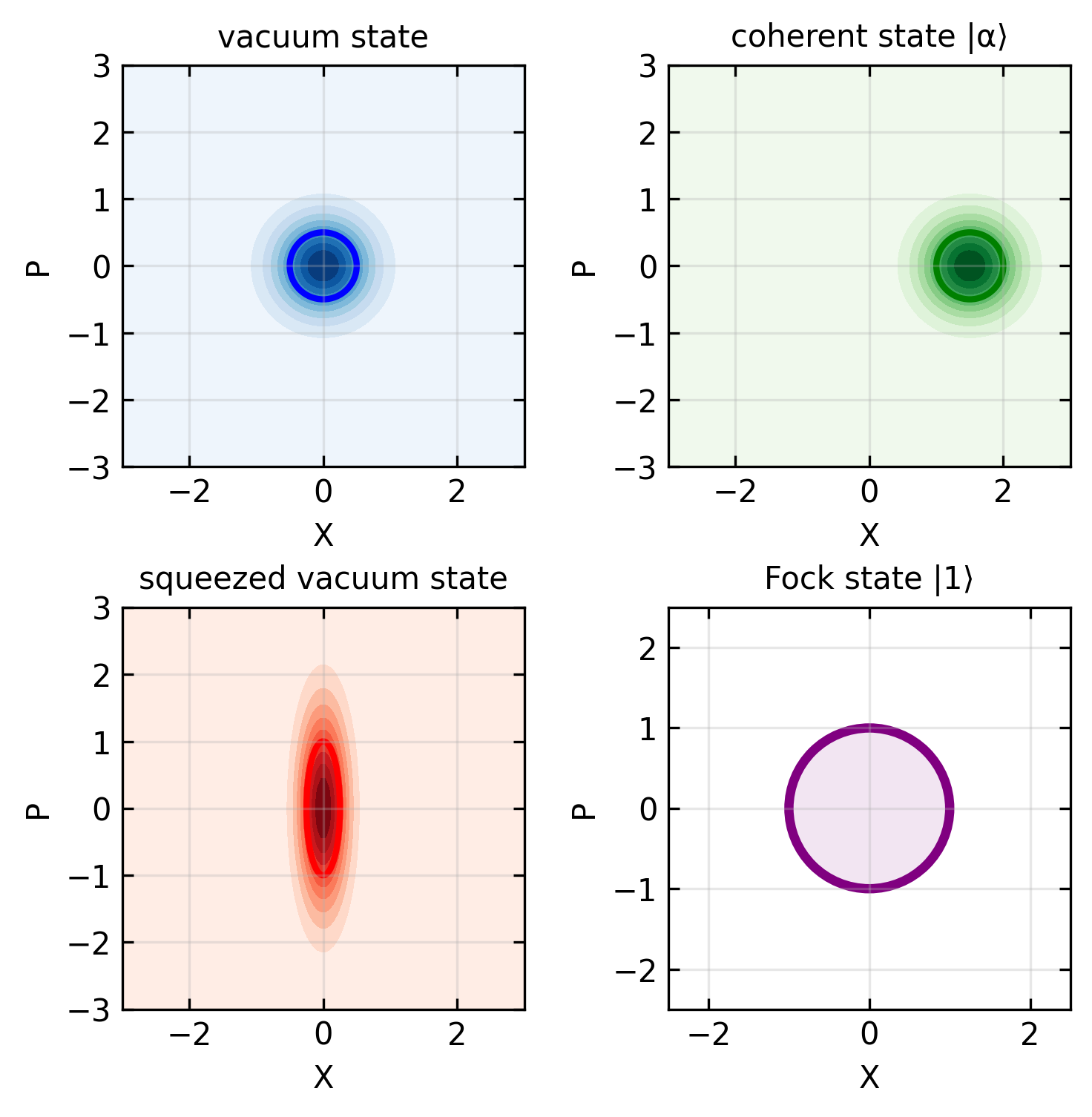
The electromagnetic field can be visualized in a phase space with quadratures as axes. Different quantum states appear as characteristic distributions in this phase space, as illustrated in the figure below:

Code
import numpy as np
import matplotlib.pyplot as plt
from matplotlib.patches import Ellipse
import matplotlib.gridspec as gridspec
from matplotlib.colors import LinearSegmentedColormap

# Create figure with 2x2 grid
fig = plt.figure(figsize=get_size(14, 14))
gs = gridspec.GridSpec(2, 2, figure=fig)

# Function to create 2D Gaussian distribution
def gaussian_2d(x, y, x0, y0, sigma_x, sigma_y):
    return np.exp(-((x-x0)**2/(2*sigma_x**2) + (y-y0)**2/(2*sigma_y**2)))

# Function to approximate Wigner function for Fock state
def fock_wigner_approx(x, y, n):
    r_squared = x**2 + y**2
    # Approximate the Fock state Wigner function
    if n == 0:  # Vacuum state
        return np.exp(-r_squared)
    elif n == 1:  # Single photon
        return (2*r_squared - 1) * np.exp(-r_squared)
    else:  # Higher photon number
        # Use Laguerre polynomials approximation
        result = (2*r_squared - 2*n - 1) * np.exp(-r_squared)
        return result * (-1)**n

# Create coordinate grid
x = np.linspace(-3, 3, 100)
y = np.linspace(-3, 3, 100)
X, Y = np.meshgrid(x, y)

# 1. Vacuum state (circular uncertainty at origin)
ax1 = fig.add_subplot(gs[0, 0])
vacuum = gaussian_2d(X, Y, 0, 0, 0.5, 0.5)
contour1 = ax1.contourf(X, Y, vacuum, levels=10, cmap='Blues')
ax1.add_patch(Ellipse((0, 0), 1.0, 1.0, fill=False, color='blue', linestyle='-', linewidth=2))
ax1.set_xlabel('X')
ax1.set_ylabel('P')
ax1.set_title('vacuum state')
ax1.grid(True, alpha=0.3)
ax1.set_aspect('equal')

# 2. Coherent state (displaced circular uncertainty)
ax2 = fig.add_subplot(gs[0, 1])
alpha_x, alpha_y = 1.5, 0  # Displacement in X direction
coherent = gaussian_2d(X, Y, alpha_x, alpha_y, 0.5, 0.5)
contour2 = ax2.contourf(X, Y, coherent, levels=10, cmap='Greens')
ax2.add_patch(Ellipse((alpha_x, alpha_y), 1.0, 1.0, fill=False, color='green', linestyle='-', linewidth=2))
ax2.set_xlabel('X')
ax2.set_ylabel('P')
ax2.set_title('coherent state |α⟩')
ax2.grid(True, alpha=0.3)
ax2.set_aspect('equal')

# 3. Squeezed state (elliptical uncertainty)
ax3 = fig.add_subplot(gs[1, 0])
squeezed = gaussian_2d(X, Y, 0, 0, 0.25, 1.0)  # Squeezed in X, anti-squeezed in P
contour3 = ax3.contourf(X, Y, squeezed, levels=10, cmap='Reds')
ax3.add_patch(Ellipse((0, 0), 0.5, 2.0, fill=False, color='red', linestyle='-', linewidth=2))
ax3.set_xlabel('X')
ax3.set_ylabel('P')
ax3.set_title('squeezed vacuum state')
ax3.grid(True, alpha=0.3)
ax3.set_aspect('equal')

# 4. Fock state (n=1 photon state)
ax4 = fig.add_subplot(gs[1, 1])
# For Fock state |1⟩, just draw a circle representing the ring-like distribution
ax4.add_patch(plt.Circle((0, 0), 1.0, fill=False, color='purple', linestyle='-', linewidth=3))
# Add a light fill to indicate the ring-like nature
ax4.add_patch(plt.Circle((0, 0), 1.0, fill=True, color='purple', alpha=0.1))
ax4.set_xlabel('X')
ax4.set_ylabel('P')
ax4.set_xlim(-2.5, 2.5)
ax4.set_ylim(-2.5, 2.5)
ax4.set_title('Fock state |1⟩')
ax4.grid(True, alpha=0.3)
ax4.set_aspect('equal')

fig.subplots_adjust(wspace=0.35, hspace=0.35)
Figure 2— Quadrature phase space representations of different quantum states

The figure above illustrates the key characteristics of different quantum states in phase space:

  1. Vacuum State: A circular Gaussian distribution centered at the origin, with equal minimum uncertainty in both quadratures.

  2. Coherent States \(|\alpha\rangle\): The same circular Gaussian distribution as the vacuum state, but displaced from the origin to a point \((\langle\hat{X}\rangle, \langle\hat{P}\rangle) = (\sqrt{2}|\alpha|\cos\phi, \sqrt{2}|\alpha|\sin\phi)\). This displacement represents a non-zero field amplitude.

  3. Squeezed States: Elliptical Gaussian distributions, with reduced uncertainty in one quadrature at the expense of increased uncertainty in the other.

  4. Fock States: Distributions with circular symmetry around the origin that exhibit a non-Gaussian “ring-like” pattern. These can exhibit negative values in the Wigner function, which is a quintessential signature of non-classical light.

This phase space representation provides a powerful visualization tool for understanding quantum states of light and their behavior under various transformations. It illustrates how classical and quantum descriptions connect: classical states correspond to points in phase space, while quantum states correspond to distributions with minimum areas constrained by the uncertainty principle. The quadrature framework is essential for understanding advanced concepts like quantum teleportation, continuous variable quantum computing, and precision measurements beyond the standard quantum limit.

Quantum States of Light

Fock States

Fock states \(|n\rangle\) represent exactly \(n\) photons in a mode. They are eigenstates of the number operator:

\[\hat{n}|n\rangle = n|n\rangle\]

Properties of Fock states:

  • Definite energy: \(E_n = \hbar\omega(n + \frac{1}{2})\)
  • Indefinite phase
  • Highly non-classical (no classical analog)
  • Exhibit sub-Poissonian photon statistics

Think of Fock states as precisely counted collections of identical photons, like having exactly 3 identical marbles in a box. This precise counting is fundamentally different from classical light, where intensity varies continuously (like water flowing from a tap). A single-photon Fock state (\(|1\rangle\)) is what we use in quantum cryptography and quantum computing - it’s literally “just one photon.” Remarkably, while we know exactly how many photons are present in a Fock state, we have no information about their phase - it’s completely random. This is similar to knowing exactly how many people are in a room but having no idea what direction they’re facing.

The experimental generation of pure Fock states, particularly the single-photon state \(|1\rangle\), presents significant challenges. Several types of single-photon sources have been developed:

  1. Attenuated lasers: The simplest approach uses highly attenuated coherent light, but these are imperfect sources as they follow Poisson statistics with non-zero probability of containing multiple photons.

  2. Spontaneous parametric down-conversion (SPDC): A nonlinear optical process where one photon splits into two entangled photons. By detecting one photon (heralding), we can verify its partner exists, approximating a single-photon state.

  3. Quantum dots: Semiconductor nanostructures that emit single photons when electrically or optically excited, behaving like artificial atoms with discrete energy levels.

  4. Color centers in solids: Defects in crystal structures (like nitrogen-vacancy centers in diamond) that emit single photons when excited.

  5. Single atoms or ions in cavities: Trapped atoms that emit exactly one photon during controlled transitions between energy levels.

The ideal single-photon source would produce photons on-demand with high efficiency, perfect indistinguishability, and zero probability of multi-photon events. Current research focuses on improving these metrics for quantum information applications.

Coherent States

Coherent states \(|\alpha\rangle\) are the quantum states that most closely resemble classical light. They are eigenstates of the annihilation operator:

\[\hat{a}|\alpha\rangle = \alpha|\alpha\rangle\]

Properties of coherent states:

  • Minimum uncertainty states
  • Poissonian photon statistics
  • Indefinite photon number
  • Well-defined phase
  • Generated by ideal lasers

You can think of coherent states as the quantum equivalent of a perfect laser beam. Unlike the precisely counted photons in Fock states, coherent states are more like a crowd of people arriving at a subway station - we don’t know exactly how many will arrive in the next minute (the photon number is uncertain), but they arrive at a steady average rate with a specific pattern of fluctuations (Poissonian statistics). If Fock states are like having exactly 5 dollars, coherent states are like having about 5 dollars on average, sometimes a bit more, sometimes less. The trade-off is that coherent states have a well-defined phase - like knowing all the people in our subway station are walking in the same direction, even if we don’t know exactly how many people there are.

Lasers are the physical realization of coherent states in quantum optics. The stimulated emission process in lasers naturally produces light with high coherence both temporally (well-defined frequency) and spatially (well-defined direction). This coherence corresponds directly to the well-defined phase property of coherent states. While an ideal laser would produce a perfect coherent state, real lasers approach this ideal quite closely, especially when operating well above threshold with proper stabilization. The quantum fluctuations in laser light manifest as the shot noise limit in precision measurements, representing the fundamental uncertainty inherent in coherent states.

A coherent state can be expressed as a superposition of Fock states:

\[|\alpha\rangle = e^{-|\alpha|^2/2}\sum_{n=0}^{\infty}\frac{\alpha^n}{\sqrt{n!}}|n\rangle\]

Beam Splitter Transformation

A beam splitter is a fundamental optical element that can generate quantum entanglement. Physically, it consists of a partially reflective interface (often a thin metallic layer on glass) that splits an incident beam of light into reflected and transmitted components. In quantum optics, this simple device becomes a powerful tool for creating non-classical correlations between photons.

For a beam splitter with arbitrary reflection and transmission coefficients (r and t), the transformation can be represented by a unitary matrix:

\[\begin{pmatrix} \hat{c} \\ \hat{d} \end{pmatrix} = \begin{pmatrix} t & r \\ r & -t \end{pmatrix} \begin{pmatrix} \hat{a} \\ \hat{b} \end{pmatrix}\]

where the unitarity conditions require \(|t|^2 + |r|^2 = 1\) and \(t^*r + tr^* = 0\). The most common case is a 50:50 beam splitter where \(|t|^2 = |r|^2 = 1/2\).

In the Schrödinger picture, focusing on creation operators for a 50:50 beam splitter, we have:

\[\hat{c}^\dagger = \frac{1}{\sqrt{2}}(\hat{a}^\dagger + \hat{b}^\dagger)\] \[\hat{d}^\dagger = \frac{1}{\sqrt{2}}(\hat{a}^\dagger - \hat{b}^\dagger)\]

where \(\hat{a}^\dagger\) and \(\hat{b}^\dagger\) are creation operators for the input ports, and \(\hat{c}^\dagger\) and \(\hat{d}^\dagger\) are for the output ports.

These transformations preserve the commutation relations, ensuring that \([\hat{c},\hat{c}^\dagger] = [\hat{d},\hat{d}^\dagger] = 1\) and \([\hat{c},\hat{d}^\dagger] = [\hat{d},\hat{c}^\dagger] = 0\), which can be verified by direct substitution.

The beam splitter evolution can also be described by a unitary operator that expresses how input states transform into output states:

\[\hat{U}_{BS} = \exp[\theta(\hat{a}^\dagger\hat{b}e^{-i\phi} - \hat{a}\hat{b}^\dagger e^{i\phi})]\]

This operator has a physical interpretation that directly relates to how a beam splitter works:

  • The operator describes the coupling between input modes a and b that creates the mixed output state
  • It represents the quantum interference process within the beam splitter that transforms input fields into output fields
  • The terms \(\hat{a}^\dagger\hat{b}\) and \(\hat{a}\hat{b}^\dagger\) represent the mode mixing - they describe how the two input modes become correlated and interfere with each other inside the beam splitter
  • The parameter \(\theta\) controls the splitting ratio: \(\theta = \pi/4\) gives a 50:50 beam splitter, while other values create uneven splitting
  • The phase factor \(\phi\) determines the relative phase between reflection and transmission

When this unitary operator acts on an input state (such as one photon in mode a and none in mode b), it transforms the input into an output state that is a quantum superposition across both output ports. The coupling terms in the exponent are what create this superposition - they mathematically describe how the input modes interfere within the beam splitter to produce the characteristic photon distribution at the outputs.

Hong-Ou-Mandel Effect

The Hong-Ou-Mandel (HOM) effect, first demonstrated experimentally in 1987, is a quintessential quantum interference phenomenon that has no classical analog. It occurs when two identical single photons enter a 50:50 beam splitter simultaneously from different input ports. This effect provides a concrete demonstration of the mode mixing described by the beam splitter unitary operator - the coupling terms \(\hat{a}^\dagger\hat{b}\) and \(\hat{a}\hat{b}^\dagger\) in the operator create correlations between the input modes that lead to this remarkable interference behavior.

Consider a state with one photon in each input port: \(|1_a, 1_b\rangle = \hat{a}^\dagger \hat{b}^\dagger |0\rangle\).

After passing through the beam splitter, this state transforms according to the mode mixing relationships. We apply the beam splitter transformations:

\[\hat{c}^\dagger = \frac{1}{\sqrt{2}}(\hat{a}^\dagger + \hat{b}^\dagger), \quad \hat{d}^\dagger = \frac{1}{\sqrt{2}}(\hat{a}^\dagger - \hat{b}^\dagger)\]

These transformation equations encode the fundamental physics: each output mode is a quantum superposition of both input modes. The physical meaning is: - Output c receives contributions from both inputs in phase (+ sign): light from input a (transmitted) and input b (reflected) interfere constructively - Output d receives contributions from both inputs out of phase (- sign): the same pathways now have a relative phase difference that can lead to destructive interference - The 1/√2 factors ensure energy conservation and equal splitting probability - The different signs between outputs create the interference patterns that lead to quantum effects like photon bunching

Starting with the input state \(\hat{a}^\dagger \hat{b}^\dagger |0\rangle\), we need to express this in terms of the output modes. We can invert the beam splitter relations to get:

\[\hat{a}^\dagger = \frac{1}{\sqrt{2}}(\hat{c}^\dagger + \hat{d}^\dagger), \quad \hat{b}^\dagger = \frac{1}{\sqrt{2}}(\hat{c}^\dagger - \hat{d}^\dagger)\]

Substituting these into our input state:

\[\hat{a}^\dagger \hat{b}^\dagger |0\rangle = \frac{1}{\sqrt{2}}(\hat{c}^\dagger + \hat{d}^\dagger) \cdot \frac{1}{\sqrt{2}}(\hat{c}^\dagger - \hat{d}^\dagger)|0\rangle = \frac{1}{2}(\hat{c}^\dagger + \hat{d}^\dagger)(\hat{c}^\dagger - \hat{d}^\dagger)|0\rangle\]

Expanding the product:

\[= \frac{1}{2}[(\hat{c}^\dagger)^2 - \hat{c}^\dagger\hat{d}^\dagger + \hat{d}^\dagger\hat{c}^\dagger - (\hat{d}^\dagger)^2]|0\rangle\]

Since creation operators for different modes commute (\(\hat{c}^\dagger\hat{d}^\dagger = \hat{d}^\dagger\hat{c}^\dagger\)), the middle terms cancel:

\[= \frac{1}{2}[(\hat{c}^\dagger)^2 - (\hat{d}^\dagger)^2]|0\rangle\]

Simplifying and normalizing:

\[\frac{1}{\sqrt{2}}(|2_c, 0_d\rangle - |0_c, 2_d\rangle)\]

This is an entangled state where both photons exit together through the same output port, with equal probability of finding both photons in either output. Remarkably, the probability of finding one photon in each output port is zero—a purely quantum effect known as the Hong-Ou-Mandel effect or photon bunching. This bunching behavior emerges directly from the mode mixing: the quantum interference created by the beam splitter’s coupling of input modes results in destructive interference for the “one photon per output” amplitude, while constructive interference occurs for the “both photons in same output” amplitudes.

To appreciate how unusual this behavior is, consider two identical red balls rolling toward a fork in the road. Classically, each ball would randomly choose one path or the other, and sometimes they’d separate. But quantum mechanically, if these were photons, they would always choose the same path. This photon bunching arises from their bosonic nature and quantum interference.

Experimentally, the HOM effect is observed by varying the relative arrival time of the two photons at the beam splitter using a delay line. When the photons arrive at different times, they behave independently, and coincidence detections occur 50% of the time. However, as the temporal overlap increases, the coincidence rate drops, reaching zero for perfectly indistinguishable photons. This creates the characteristic “HOM dip” in the coincidence count rate:

\[R_c(\Delta t) = R_0\left(1 - V\exp\left(-\frac{(\Delta t)^2}{2\sigma^2}\right)\right)\]

where \(V\) is the visibility (ideally 1 for perfect indistinguishability) and \(\sigma\) relates to the coherence time of the photons.

The HOM effect serves as:

  1. A highly sensitive method to measure timing differences down to femtoseconds
  2. A test of photon indistinguishability in all degrees of freedom (frequency, polarization, spatial mode)
  3. A fundamental building block for linear optical quantum computing
  4. A tool for characterizing single-photon sources

Phase-Based Understanding and Quantum Paths

The HOM effect can be understood more intuitively through probability amplitudes and the concept of indistinguishable paths.

For a 50:50 beam splitter with energy conservation and time-reversal symmetry, there are two common phase conventions in the literature:

Convention 1 (Phase on Transmission - used here): - Reflection amplitude: \(r = 1/\sqrt{2}\) (real) - Transmission amplitude: \(t = i/\sqrt{2}\) (π/2 phase shift)

Convention 2 (Phase on Reflection - also common): - Reflection amplitude: \(r = i/\sqrt{2}\) (π/2 phase shift) - Transmission amplitude: \(t = 1/\sqrt{2}\) (real)

Both conventions are physically correct and lead to identical experimental predictions. The choice depends on the specific beam splitter design (dielectric vs metallic coating), measurement reference frame, and theoretical convenience. The essential physics is that one of the two processes (reflection or transmission) must acquire a π/2 phase shift to satisfy unitarity and energy conservation. We use Convention 1 in this analysis.

Connection to Fresnel Equations: The phase factors in quantum beam splitters have their origin in classical electromagnetic theory through the Fresnel equations. When light reflects from or transmits through an interface, the Fresnel equations predict phase shifts that depend on: - The refractive indices of the materials - The angle of incidence - The polarization of the light

For a dielectric beam splitter (like a glass plate with metallic coating), the Fresnel equations can predict phase shifts of 0, π/2, or π depending on the specific geometry and materials. However, the quantum beam splitter phase conventions are often chosen for mathematical convenience rather than direct correspondence to the Fresnel phases. The key constraint is that the beam splitter matrix must be unitary, which requires a specific phase relationship between reflection and transmission amplitudes.

In practice, real beam splitters may have phase shifts that don’t exactly match either convention due to: - Coating properties and thickness - Wavelength dependence - Angular dependence - Substrate effects

For quantum optics calculations, we typically use the idealized phase conventions and then account for real device characteristics through calibration measurements when necessary.

With two photons entering from different ports, four possible pathways must be considered:

  1. Photon from port a reflects to port c, photon from port b reflects to port d:

    • Amplitude = \(r \cdot r = 1/2\)
    • Final state: \(|1_c, 1_d\rangle\)
  2. Photon from port a transmits to port d, photon from port b transmits to port c:

    • Amplitude = \(t \cdot t = (i/\sqrt{2})^2 = -1/2\)
    • Final state: \(|1_c, 1_d\rangle\)
  3. Both photons exit from port c (one reflects, one transmits):

    • Amplitude = \(r \cdot t = i/2\)
    • Final state: \(|2_c, 0_d\rangle\)
  4. Both photons exit from port d (one reflects, one transmits):

    • Amplitude = \(t \cdot r = i/2\)
    • Final state: \(|0_c, 2_d\rangle\)

The critical quantum interference occurs between pathways 1 and 2, which lead to the same final state \(|1_c, 1_d\rangle\). The total amplitude for this outcome is:

\[A_{|1_c, 1_d\rangle} = r^2 + t^2 = 1/2 + (-1/2) = 0\]

This perfect destructive interference explains why one photon is never observed in each output port.

For the bunched outcomes, the amplitudes are:

\[A_{|2_c, 0_d\rangle} = rt = i/2\] \[A_{|0_c, 2_d\rangle} = tr = i/2\]

Squaring these amplitudes gives the probabilities:

  • Probability of one photon in each output port: \(|0|^2 = 0\)
  • Probability of both photons in port c: \(|i/2|^2 = 1/4\)
  • Probability of both photons in port d: \(|i/2|^2 = 1/4\)

When normalized (multiplying by 2), there is a 50% probability for each bunched outcome.

Generalizations and Applications

The beam splitter entanglement mechanism extends beyond the two-photon case. For example, with input state \(|n_a, m_b\rangle\), the output becomes a complex superposition of states \(|k_c, (n+m-k)_d\rangle\) weighted by binomial coefficients.

The beam splitter’s entangling capabilities are utilized in:

  1. Bell state generation: By placing a source of entangled photon pairs (e.g., from spontaneous parametric down-conversion) at one input port and vacuum at the other, beam splitters can help prepare specific Bell states for quantum communication protocols.

  2. Quantum teleportation: Beam splitters are essential components in Bell-state analyzers used for quantum teleportation, where they create the necessary entanglement between photons.

  3. Boson sampling: A computational problem where multiple photons are sent through a network of beam splitters, creating a complex entangled state whose photon statistics are believed to be classically hard to simulate.

  4. Quantum metrology: HOM interference enables quantum-enhanced measurements that can exceed classical precision limits, particularly in quantum imaging and sensing applications.

The quantum interference at a beam splitter thus represents one of the most elegant demonstrations of quantum mechanics, where the simple act of splitting a beam reveals the profound wave-particle duality of light and generates entanglement—a uniquely quantum resource with no classical analog.
Applications and Implications

Quantum Information Processing

The ability to generate and manipulate entangled photons provides the foundation for:

  • Quantum computing with photons
  • Quantum key distribution for secure communication
  • Quantum teleportation protocols

These quantum information applications leverage the unique properties of quantum light in ways impossible with classical systems. Quantum key distribution, for example, uses the fact that measuring a quantum state disturbs it, allowing users to detect eavesdroppers attempting to intercept communications. It’s like sending a package that changes color if anyone opens it along the way. Quantum teleportation doesn’t actually move matter faster than light as in science fiction, but rather transfers the exact quantum state from one particle to another distant particle using entanglement as a resource - somewhat like transferring a computer file from one device to another, but for quantum information that cannot be perfectly copied or measured.

Quantum Metrology

Quantum states of light can enhance measurement precision beyond classical limits: - Gravitational wave detection - Atomic clocks - Ultra-precise imaging

Fundamental Tests of Quantum Mechanics

Entangled photons allow tests of:

  • Bell’s inequalities
  • Quantum non-locality
  • The boundary between quantum and classical physics

These experiments address fundamental questions about reality itself. Bell’s inequalities provide a way to experimentally distinguish between quantum mechanics and classical theories with “hidden variables.” When violated (as experiments consistently show), they reveal that entangled photons share correlations stronger than any classical system could possibly exhibit. It’s like having two coins that always land showing the same face when flipped, even when separated by vast distances, with no hidden mechanism or prior agreement on the outcome. This “spooky action at a distance,” as Einstein called it, demonstrates that our universe doesn’t obey the local realism that seems intuitive in our everyday experience, challenging our deepest notions about the nature of reality and information.

Further Reading

  • Cohen-Tannoudji, C., Dupont-Roc, J., & Grynberg, G. (1997). Photons and Atoms: Introduction to Quantum Electrodynamics
  • Fox, M. (2006). Quantum Optics: An Introduction
  • Gerry, C. C., & Knight, P. L. (2005). Introductory Quantum Optics