This page was generated from `/home/lectures/exp3/source/notebooks/L1/Refraction.ipynb`_.
![]()
Refraction
The law of refraction is the second important law of geometrical optics. It connects the refractive index
Refractive Index
The refractive index
Snells Law
|
|---|
Fig.: Snell’s law. |
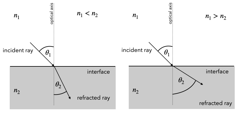
Law of Reflection (Snells Law)
The law of refraction (Snell’s law) is given for the above sketch by
In the previous section in refraction we have derived the law of reflection from Fermat’s principle. Try yourself to obtain Snell’s law with the help of Fermat’s principle. Check out the Refraction Explorer Snippet if you want to play around with Snells law. You may tray there even negative refraction.
According to Snell’s law, there is a general behavior of the corresponding angles, which you might want to remember (see also Fig. above). Consider the following cases:
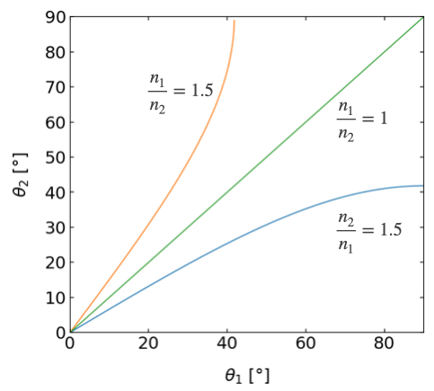
The plot below shows this result in three plots with varying incident angle and two different refractive index combinations (glass/air, ait/glass).
|
|---|
Fig.: Snells law for different combinations of refractive indices. |
Total Internal Reflection
The above diagram reveals a special case occurring when
Let’s first formalize this. Using the Snell’s law. For
for the critical angle
|
|---|
Fig.: Total internal reflection |
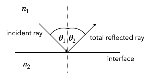
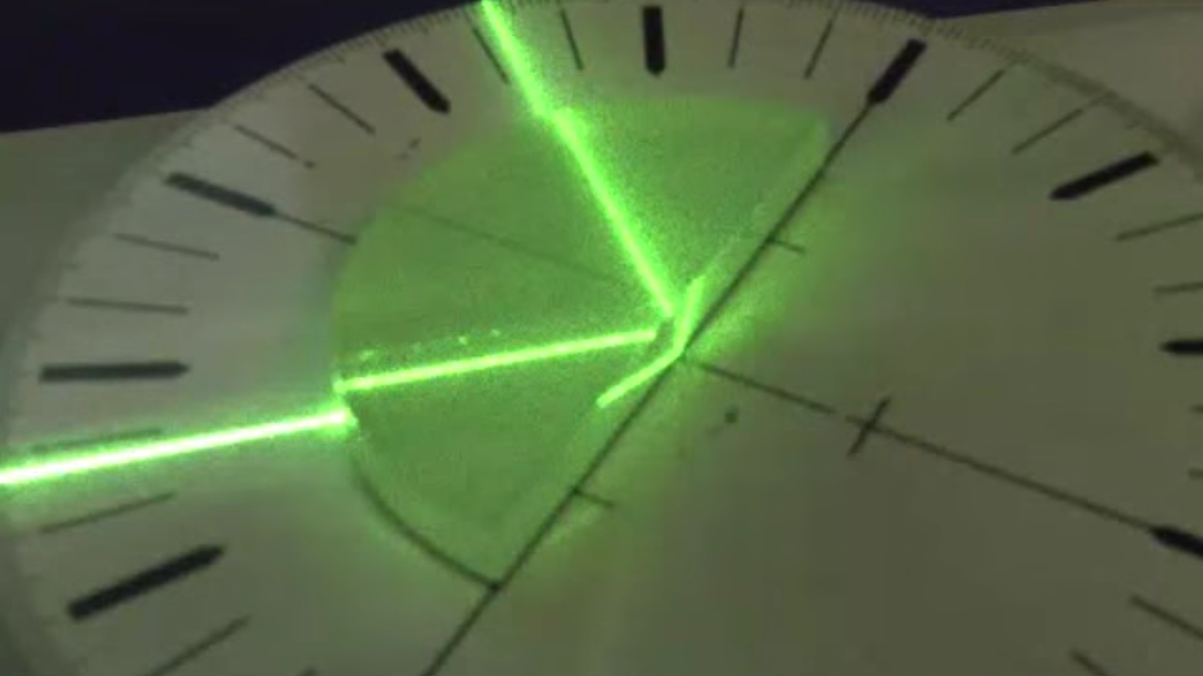
Total Internal Reflection
Total internal reflection occurs when light is passing from higher refractive index to lower refractive index materials for incidence angle larger than a critical angle
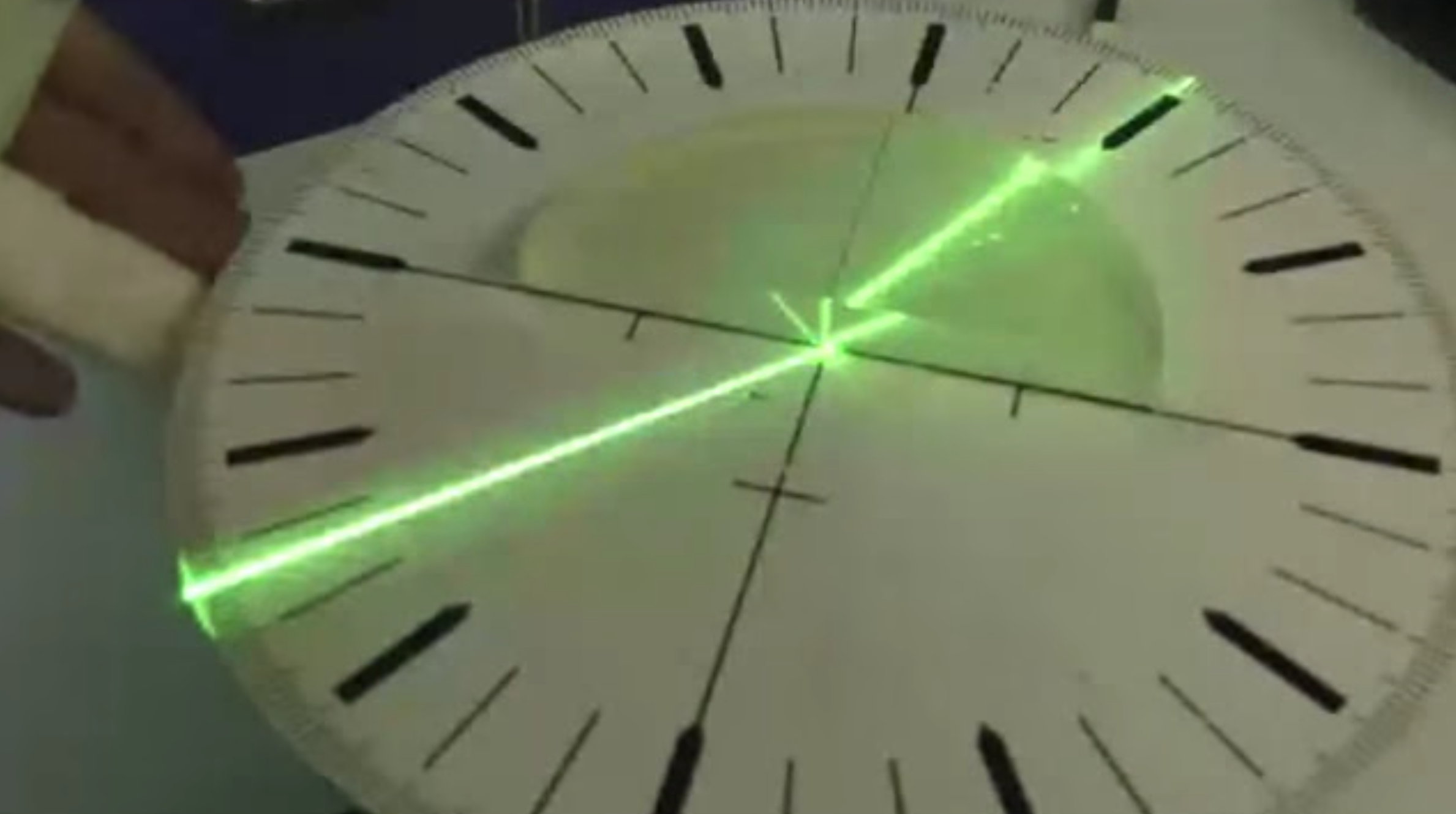
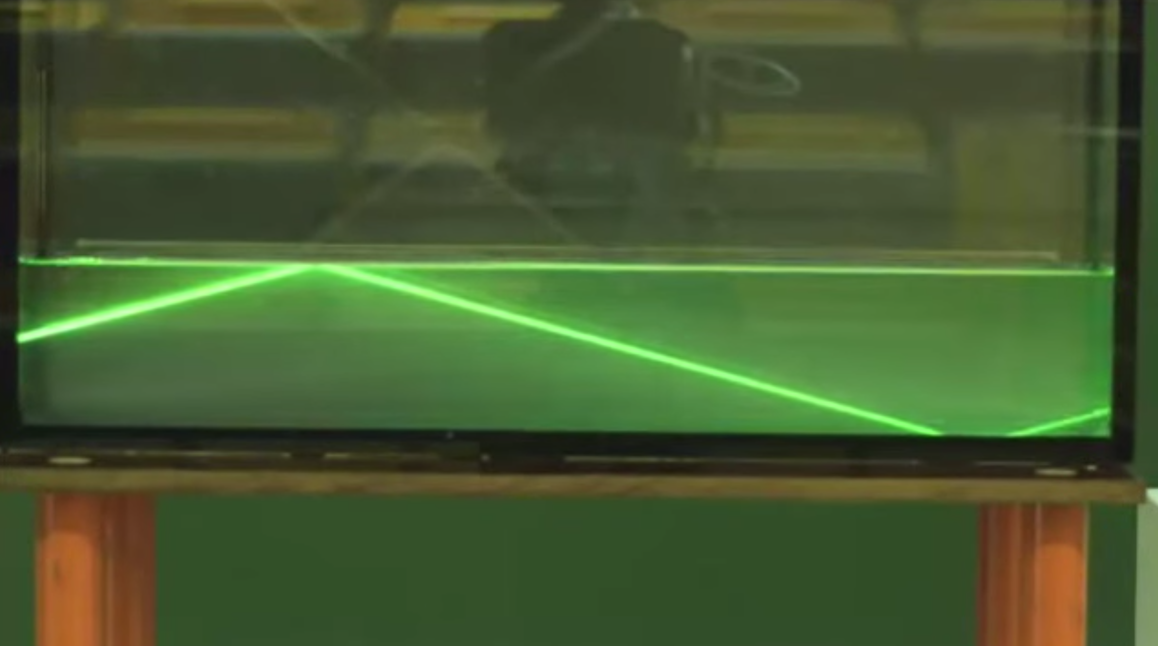
We can demonstrate total internal reflection very easily with a water basin, for example, where we couple in light from a laser from the side.
|
|---|
Fig.: Total internal reflection at a water/air interface. |
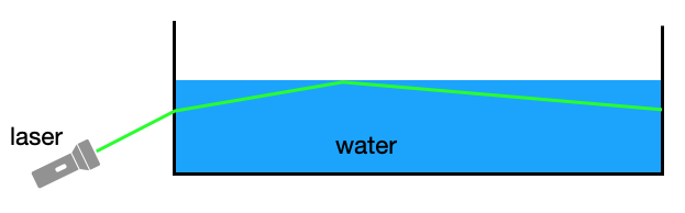
But you could try that yourself also in the bath tub diving below the water surface.
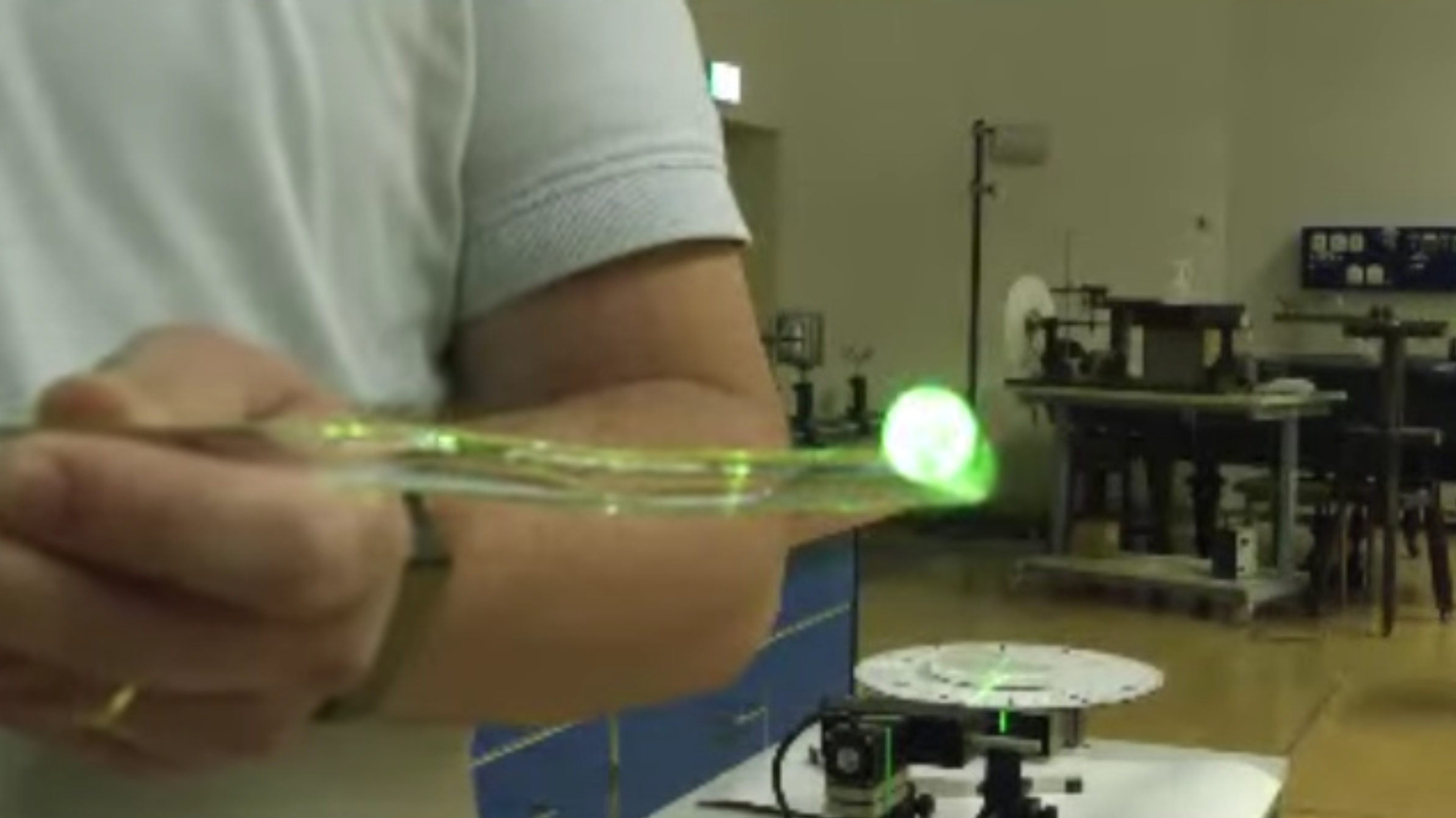
Optical Fiber Total internal reflection is very important for guiding light in telecommunications, for example. There, glass wires with a diameter from a few to several 100 µm are used to transport light. The glass wire with a central core of refractive index
|
|---|
Fig.: Total internal reflection in an optical fiber and a glass rod. |
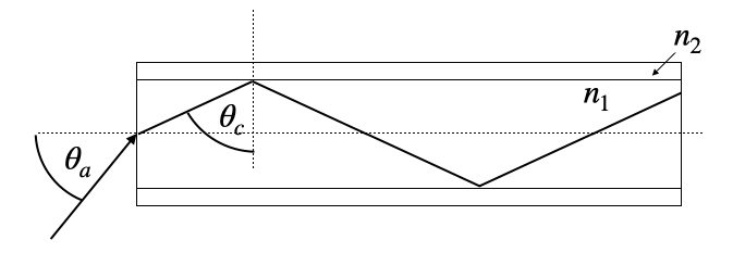
The angle
Using typical values of the refractive indices