This page was generated from `/home/lectures/exp3/source/notebooks/L9/Thin Film Interference.ipynb`_.
Thin Film Interference
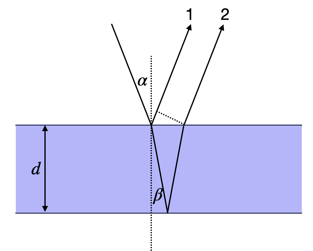
The reflection and transmission of waves on a thin film can also be regarded as an interference of two waves. A light wave is incident on a thin film as depicted below. A part of the wave is reflected on the first boundary (1). Another part is transmitted through the first boundary and reflected at the second boundary to be transmitted in the same direction (2) as the first reflected part. Note that the lines and arrows denote the direction of the wavevector
|
|---|
Fig.: Interference on a thin film considering two partial waves. |
This picture of a single reflection at each of the interfaces is certainly a simplification and in general we would have to consider an infinite number of reflections. But if we assume that the reflection is weak (e.g. 4% as for the air/glass interface), then the next reflection would just diminish the 4% to 4% of 4%, which is really weak. So the two wave interference may be a good model for weak reflections.
For the geometry shown in the figure above, we have just have a medium with
We find
where the first term contains the distance traveled by wave 2 inside the water film. The second term is the additional distance wave 1 has to travel after being reflected which is indicated by the dotted line inbetween.
We can now introduce Snells law into the calculation, as Snells law must be also valid in wave optics and also in electromagnetic optics. With
With that we can now also calculate the phase shift
You may now wonder about the second part
Phase Jump at Boundaries
Wave may experience phase jumps when being reflected.
A light wave will experience a phase jump of
A light wave will experience no phase jump when being reflected by a medium of lower refractive index.
The physical reasons will be covered when we deal with the Fresnel formulas in electromagnetic optics.
To get to know the properties of thin film interference a bit better we consider the normal incidence
In case we are searching for constructive interference, this phase shift should correspond to an integer multiple of
We would like to discuss two different situations in the following in an example. For that we either look at the thickness under which a constructive interference at a wavelength of
Fixed Wavelength
For a fixed wavelength of
Fixed Thickness
For a fixed thickness of
We can now have a look at two examples.
Example 1 - d=100 nm
If we look at a film thickness of
or
which yields for different values of
and so on. We see therefore that the longest wavelength to create constructive interference is
|
|---|
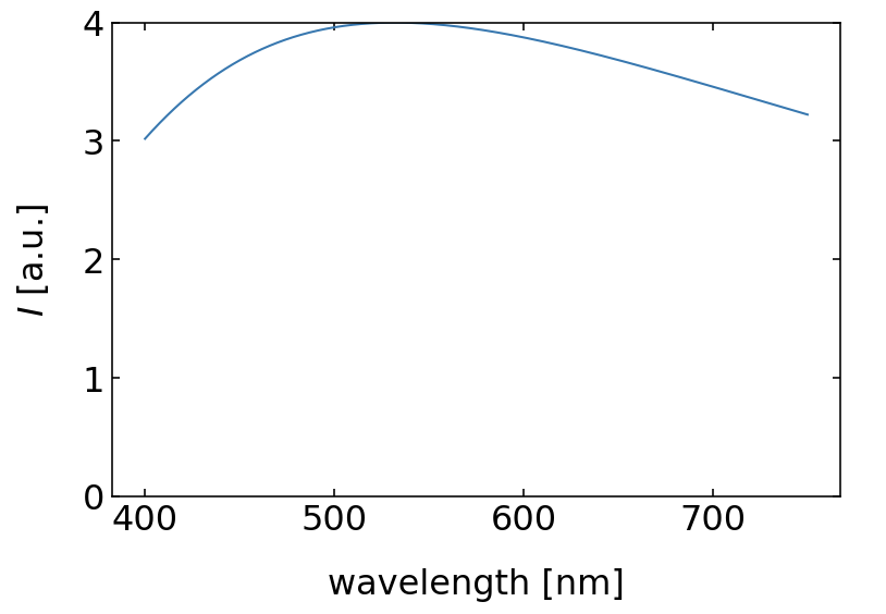
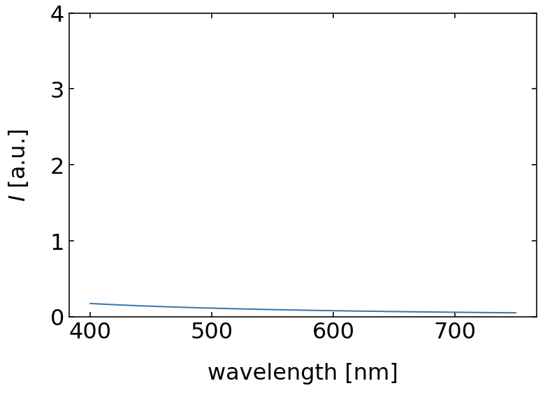
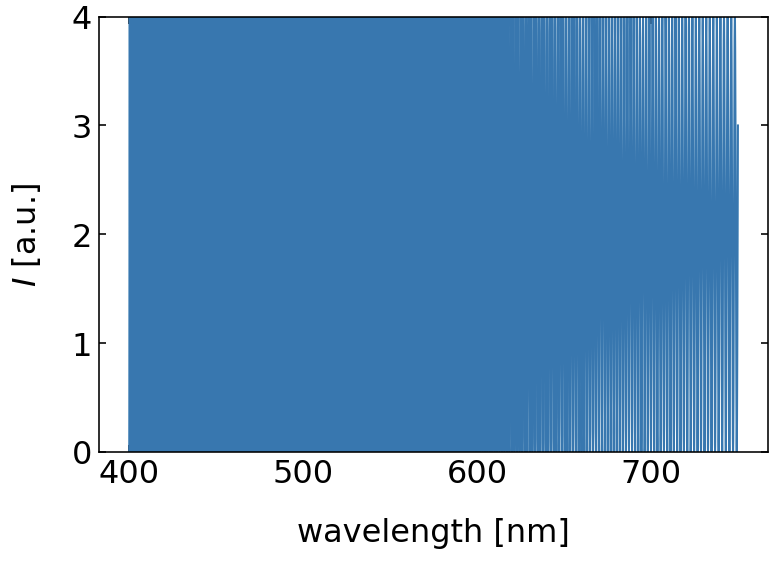
Fig.: Reflection from a 100 nm (left) and a 10 nm (right)thin water film. |
An interesting effect is appearing, when the thickness of the water film get very thin. We may ask, when is no constructive interference observed. We therefore set the wavelength of the constructive interefence to
So for film thickness of water thinner than 75 nm, there is no constructive interference of the reflected light from the two boundaries in the visible region anymore. There will be still a reflection but no specific color. If the film gets even thinner, the intensity of the reflected light is further diminished by desctructive interference and whe obtain no reflection as shown on the right side of the above figure for a
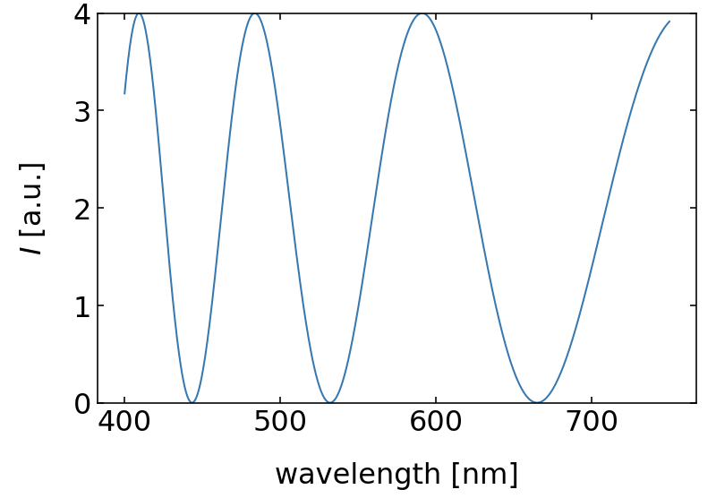
If the film gets thicker, e.g.
|
|---|
Fig.: Reflection from a 1 µm (left) and a 100 µm (right)thin water film. |
|
|---|
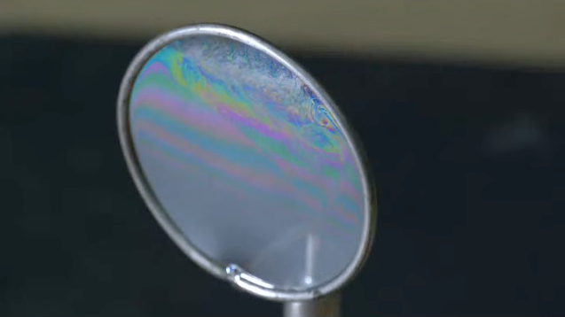
Fig.: Experimental demonstration of the reflection of white light by a thin soap film. |

