This page was generated from `/home/lectures/exp3/source/notebooks/L2/Optical Elements I.ipynb`_.
Optical Elements Part I
[29]:
## just for plotting later

import pandas as pd
import matplotlib.pyplot as plt
%matplotlib inline
%config InlineBackend.figure_format = 'retina'

plt.rcParams.update({'font.size': 12,
                     'axes.titlesize': 18,
                     'axes.labelsize': 16,
                     'axes.labelpad': 14,
                     'lines.linewidth': 1,
                     'lines.markersize': 10,
                     'xtick.labelsize' : 16,
                     'ytick.labelsize' : 16,
                     'xtick.top' : True,
                     'xtick.direction' : 'in',
                     'ytick.right' : True,
                     'ytick.direction' : 'in',})
Mirrors
Plane Mirrors
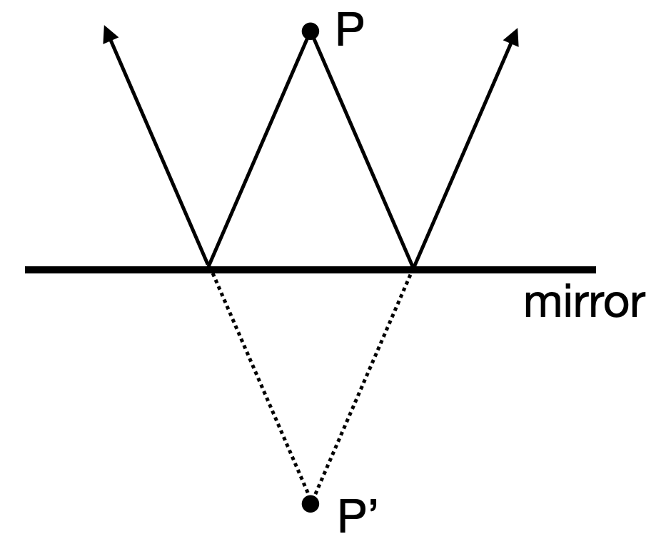
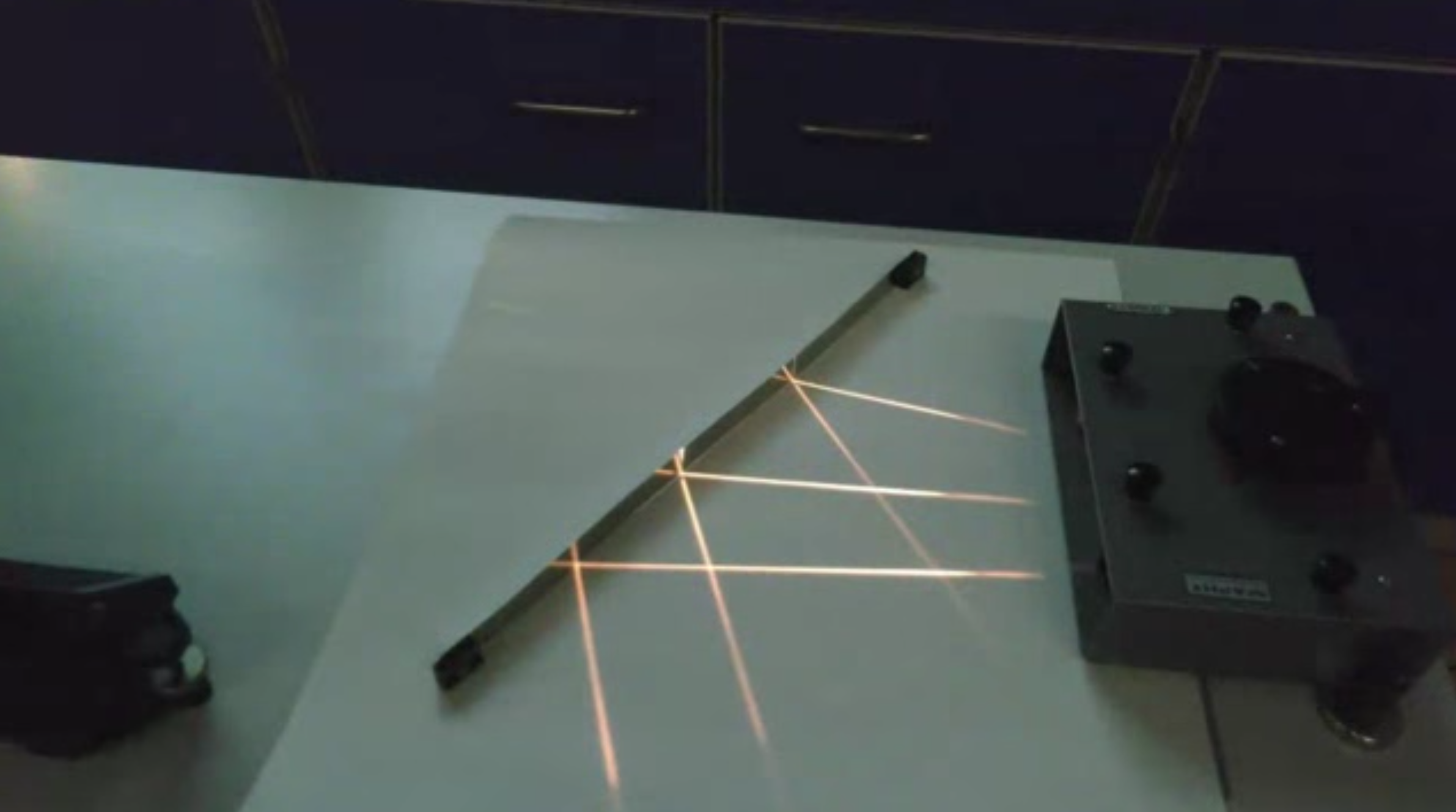
If a point
|
|---|
Fig.: Image formation on a plane mirror. |
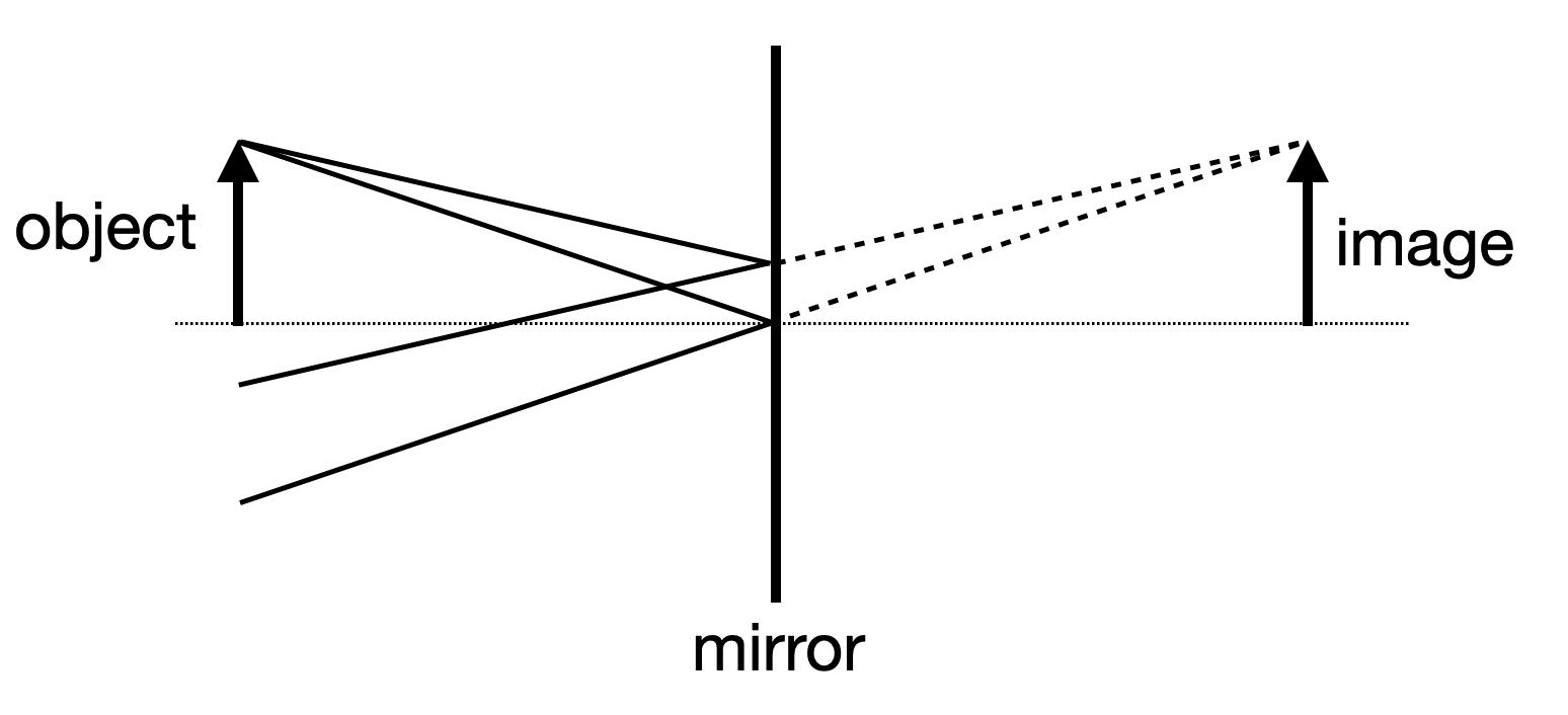
If now many point of an object emit light towards the mirror then this is also true for all of the points and the whole object appears as an image behind the mirror. Consequently, the image has the same size than the object. Therefore the magnification defined as
|
|---|
Fig.: Image formation on a plane mirror. |
Concave Mirrors
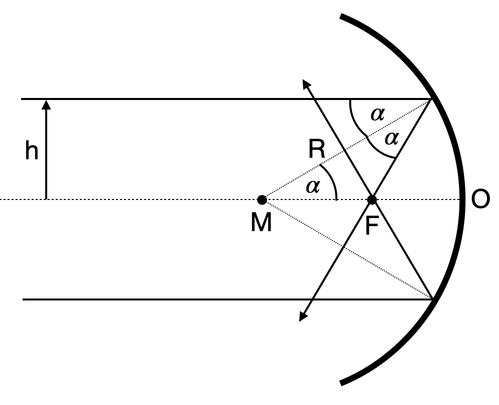
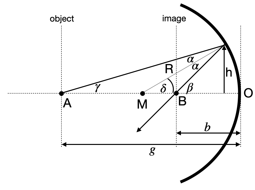
When we apply the law of reflection for a concave mirror (i.e. the reflecting side of the mirror is on the inside of the spherical surface), the light parallel to the optical axis at a distance
|
|---|
Fig.: Ray propagation on a concave mirror. |
We may calculate the position of the point
Therefore, we can also calculate the distance of the mirror surafce from the point
This distance is the so-called focal length of the concave mirror
This equation is telling us, that the focal distance is not a single value for a concave mirror. The focal distance rather changes with the distance
To obtain now an equation which predicts the point at which the reflected ray intersects the optical axis if it emerged at a point
|
|---|
Fig.: Image formation on a concave mirror. |
For this situation, we can write down immediately the following relations
Further
and
and finally
from which we obtain the imaging equation
This equation has some surprising property. It is completely independent of
Imaging Equation Concave Mirror
The sum of the inverse object and image distances equals the inverse focal length of the cocave mirror.
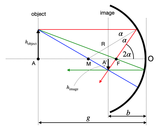
This equation now helps to construct the image of an object in front of a concave mirror and we may define 3 different rays to identify the size of an image
|
|---|
Fig.: Image formation on a concave mirror. |
In the above sketch, there are three different rays, which help us to construct the image.
red ray: parallel ray → focal ray
green ray: focal ray → parallel ray
central ray: central ray → central ray
All three reflected rays will either intersect on the same side of the mirror as the object. In this case, the image is called real image and it will be inverted as in the sketch. If the reflected rays on the other hand diverge, the appear to intersect behind the mirror. In this case, the image is called virtual image. It is located behind the mirror. There is no real intersection of rays in that case.
The intersection point further gives the size of the image. Using a ray from the tip of the object to the intersection between mirror and optical axis (O), we may easily determine the image height
As mentioned earlier, this resembles to be the magnification
With the help of the imaging equation and the magnification we may in general differentiate between the following general situations:

