This page was generated from `/home/lectures/exp3/source/notebooks/L10/FabryPerot.ipynb`_.
![]()
Fabry Perot Interferometer
We will now have a look at some applications of the multiwave interference also with changing amplitude. One of the is the Fabry-Perot interferometer, which essentially consists of two mirrors, which are brought to a distance
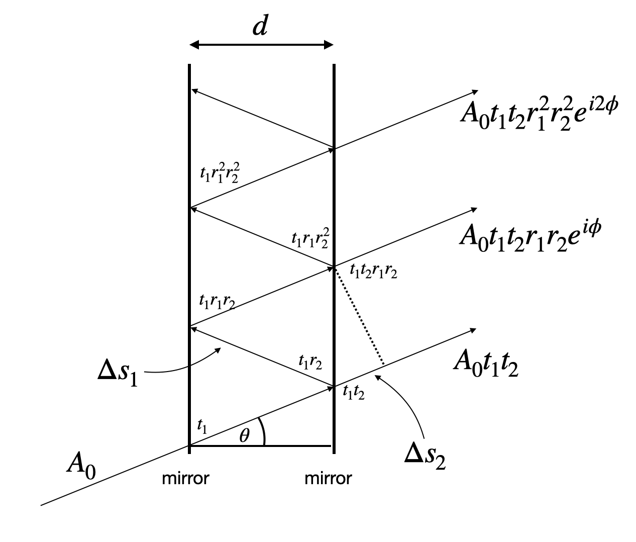
Fig.: Simplified Sketch of a Fabry-Perot Interferometer.
If light enters the Fabry Perot interferometer with an amplitude
The second transmitted wave now has a decreased amplitude as compared to the first one and reads
We could now continue like that, but we see already at this point the similarity to the multiwave interference with decreasing amplitude we have talked about in the last lecture. We would observe interference of all transmitted waves
We just have to insert the corresponding expression, i.e.
which is calculated from the path length difference
Our final formula would thus look like
and gives now the intensity as calculated during the last lecture.
|
|---|
Fig.: Fabry Perot Interferometer. |
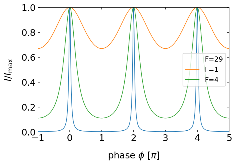
Yet, we know now that
The better the reflectivity of the mirrors (which means
Let us discuss the form of the interference peeks and the distance a bit more in detail. We have plotted so far the intensity as a function of the phase angle
We would like to have a look at the transmission in the case of normal incidence
We may then calculate the distance of the constructive interference maxima for neighboring values of the interference order
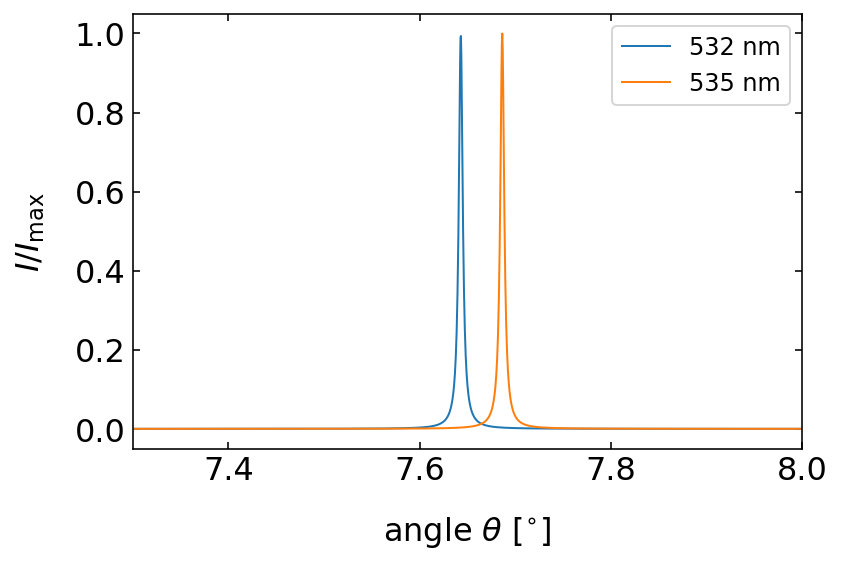
We may also do the calculation in the frequency space. A wavelength
This quantity
using the small angle approximation
This actually directly gives a definition for the Finesse.
This means that the Finesse gives us a measure for the spectral resolution of a Fabry-Perot-Interferometer. It tells us by how much the free spectral range $:nbsphinx-math:delta `:nbsphinx-math:nu $ is bigger than the width :math:Delta nu` of the interference maximum. More generally this is measured by the resolving power
where
|
|---|
Fig.: Two different wavelength interfereing constructively in a Fabry Perot interferometer. |
A specific intensity pattern is obtained when inserting a Fabry Perot interferometer in a lens system and using an extended monochromatic light source as sketched below.
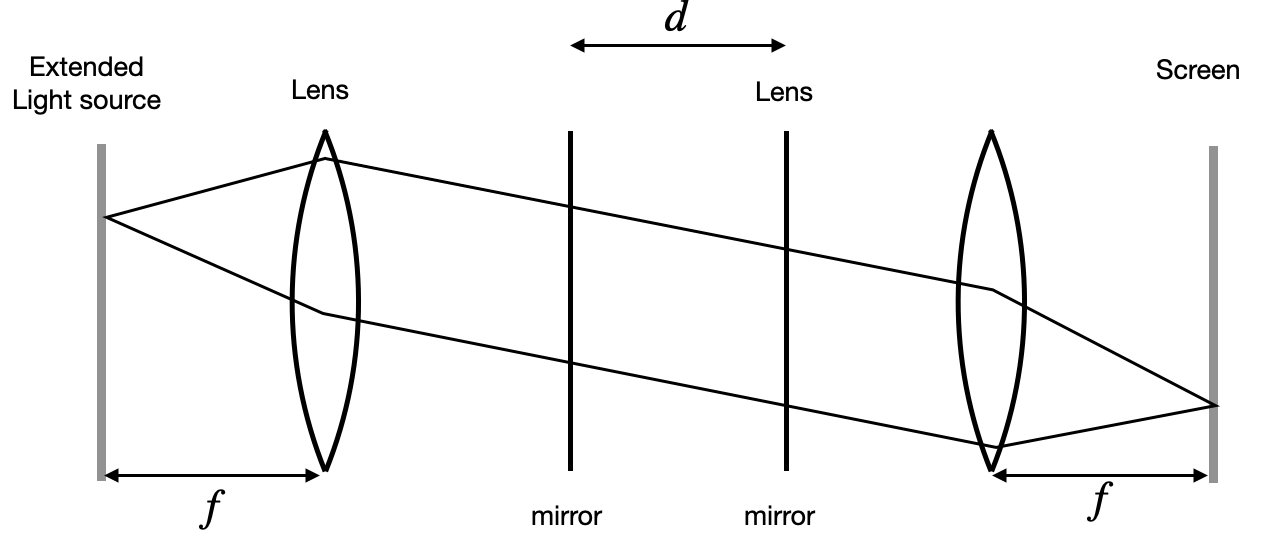
Fig.: Fabry Perot Interferometer and interferebnce pattern observed in the lecture.
In this case the interference pattern is a ring structure whgich gets denser with increasing radius as shown in the lecture (see below).
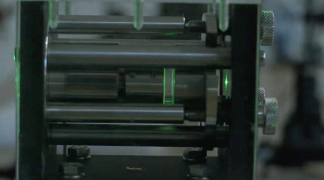
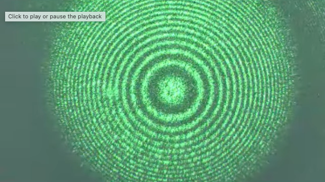
Fig.: Fabry Perot Interferometer and interferebnce pattern observed in the lecture.
Newton Rings
A similar interference pattern is also observed in the case of a hemi-spherical surface touching a planar surface as sketched in the image below.
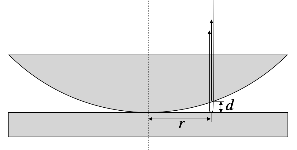
Fig.: Newton Rings. Interference of waves from a spherical and a planar surface in close contact.
If light in incident normal to the top surface, light is reflected at several surfaces. The ones we are interested in are the spherical surface and the planar surface below. The vertical distance between those points is
Under these conditions the path length difference between a wave reflected at the curved and the planar surface is
Note that the additional
Having the path length difference we can now calculate the condition for destructive interference, i.e.
where
with
for
follows. We may therefore calculate the radius
The radius of the interference fringes is thus characteristic for a certain wavelength and radius and increases with the square root of the integer
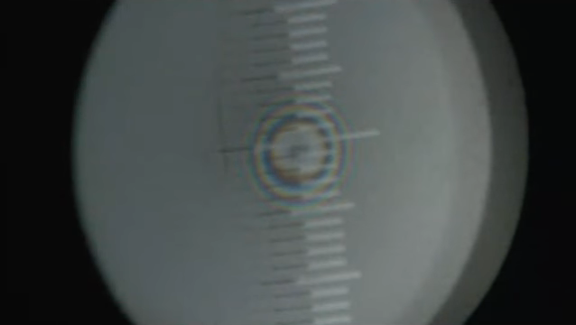
Fig.: Observation of Newton Rings using white light in the lecture.
Such patterns can be used to calculate the wavelength of light if the radius of the spherical surface is known.