This page was generated from `/home/lectures/exp3/source/notebooks/L12/Fresnel Zones.ipynb`_.
![]()
Fresnel Zones
We want to have a more general look at diffracion and just take a detour over a concept, which is called Fresnel zones. We have a look at spherical waves of a wavelength
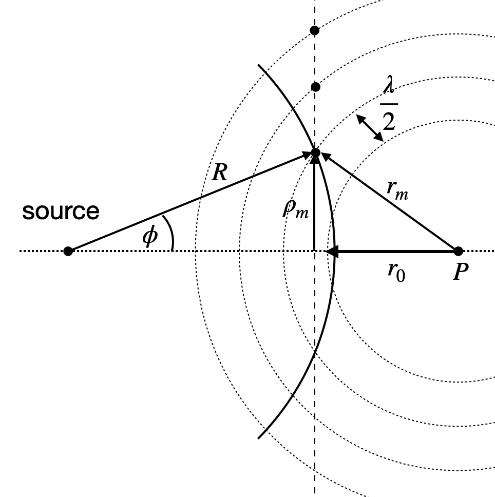
Fig.: Construction of the Fresenel Zones.
We will have a look at the intensity of the wave at a point
We will not calculate the intensity explicitly, but rather analyze the distance of the individual points on the wavefront from the point
where
according to the sketch above. This yields
For
which gives the radius of the individual zones. The width of the zones is given by
Fresnel Zone Plate
If we now fill on a glass slide the ring
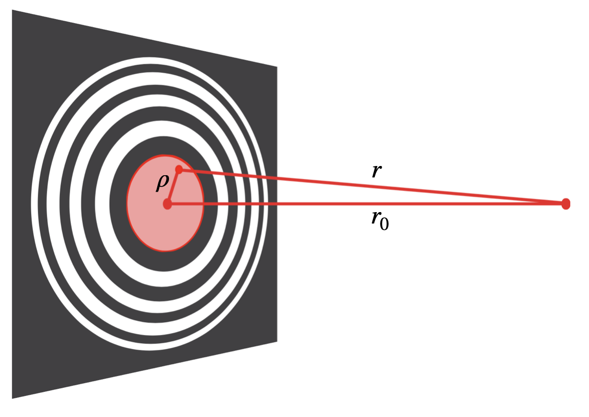
Fig.: Fresnel zone plate removing destructive interference to the point on the optical axis.
The Fresnel zones plate may be constructed by defining the inner reference zone in an arbitrary way. One may either block or transmit the direct path from the light source along the optical axis and thus have either the odd or even zones transparent.
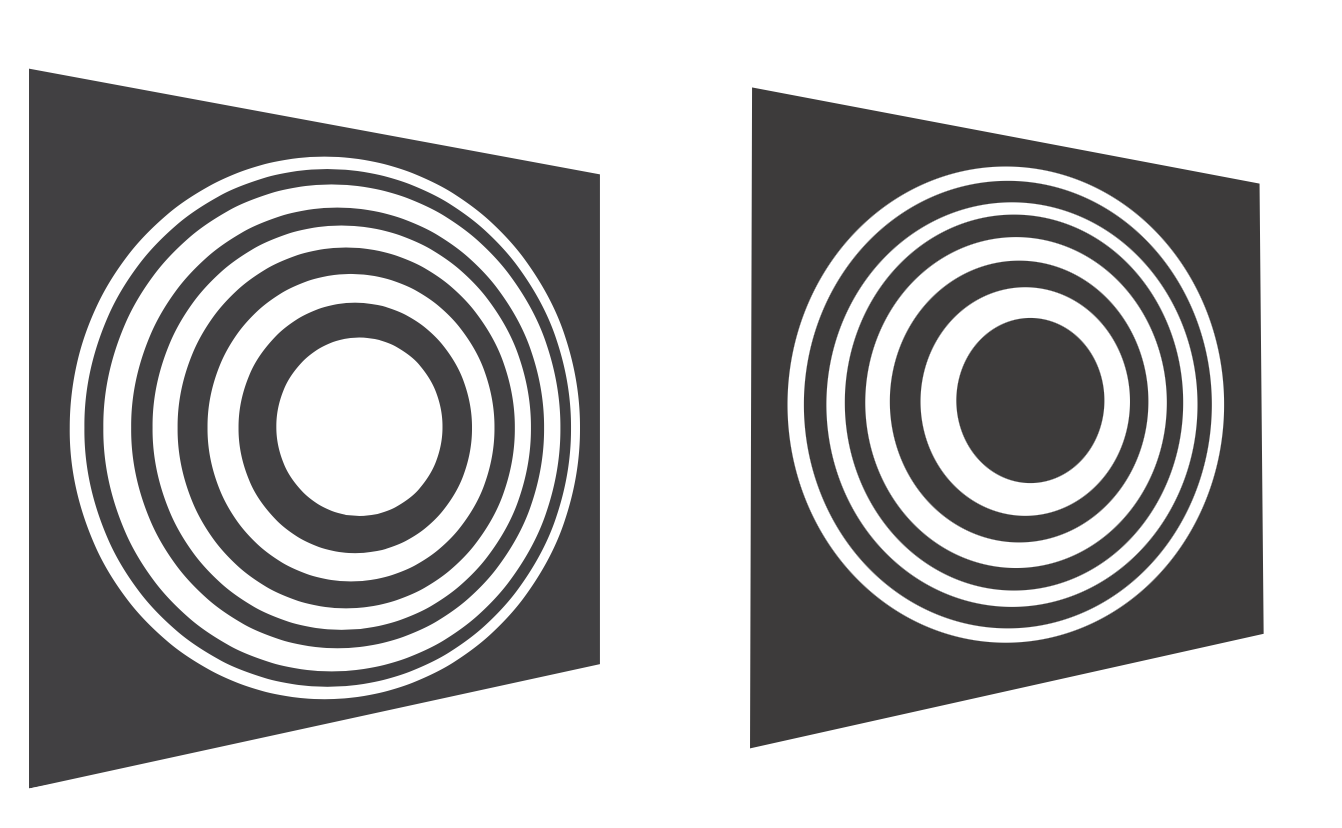
Fig.: Fresnel zone plates with odd (left) or even (right) zones transparent delivering the same result.
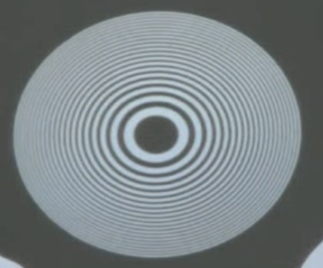
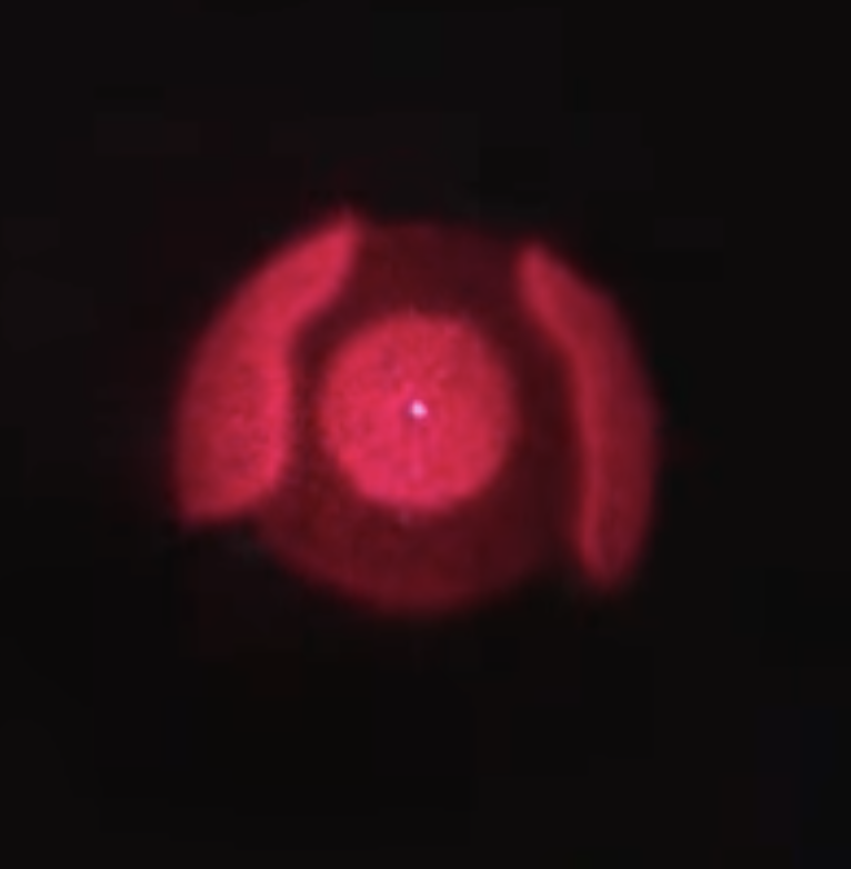
Fig.: Fresnel zone plate used in the lecture (left), which actually cracked due to the heat of the light source a second later. The Fresnel zone plate creates a focal point as visbile on the right (bright spot in the center).
Such zone plates are important for applications, when for example the focusing of radiation has to be achieved but refractive indices are not large enough to create a strong enougth refraction. This is especially true for X-ray radiation.
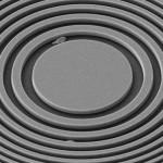
Fig.: Fresnel zone plates for X-ray radiation. Image taken from Ion beam lithography for Fresnel zone plates in X-ray microscopy - Optics Express, Vol. 21 Issue 10, pp.11747-11756 (2013).