This page was generated from `/home/lectures/exp3/source/notebooks/L18_AMA/Anisotropic Materials.ipynb`_.
![]()
Anisotropic Materials
Light propagation
So war we have only discussed isotropic materials, meaning that the speed of light was independent by the direction of light propagation in the material. Often, the light propagation is, however, not isotropic as the underlying materials have an anisotropic structure.
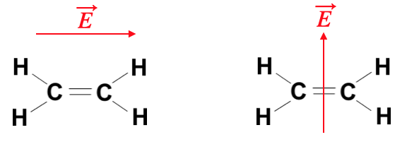
Fig.: Ethene molecules as an example for an anisotropically polarizable object. The red arrows denote the electric field directions.
Just consider the above molecule
Consequently also the susceptibility
This coordinate systems is the principle coordinate system of the tensor. The electric displacement field
and in the principle coordinate system of the tensor we obtain
From this it becomes evident, that the displacement field

Fig.:
The tensorial nature of the dielectric function has now consequences for the propagation of light. In general different symmetries are considered. If we have for example two of the diagonal elements be equal to each other
then we call the material uniaxial. The system has one optical axis. In case
we call the material biaxial and the material has two optical axes. We will have a look at the meaning of an optical axis a bit later.
A tensor as the dielectric tensor (similar to the tensor of inertia) can be geometrically represented by an ellipsoid with three different half axes as depicted below. This can be done for the refractive index or the dielectric tensor. When doing so with the refractive index, we obtain an index ellipsoid, where the half-axes correspond to the three refractive indices
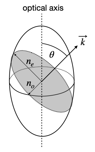
Fig.:
To find out the relevant refractive indices for a certain propagation direction on now undertakes the following steps:
chose a direction of light propagation with the direction of the wavevector
construct a plane perpendicular to the wavevector
take the intersection of this plane with the ellisoid, which is in general an ellipse
the ellipse has a long and a short axis, which correspond to the direction of the so-called normal modes
a
An optical axis is now a propagation direction, for which the refractive index does not depend on the direction of the electric field. For a biaxial material, there are two distinct directions for a propagation, while there is only one for uniaxial.
Considering now in more detail the propagation of light as a function of the direction of light propagation one obtains a dispersion relation (how the wavenumber depends on teh direction for a given frequency of light). This surface is the so-called k-surface, which in general consists of 2 sheets. This k-surface is obtained from Maxwells equations
which leads to
This equation leads to a system of equations for the components of the wavevector (
This k-surface has, for a uniaxial material, in the plane (here x-z plane) a circular and an elliptical shape, where the circular shape corresponds to the ordinary refractive index and the elliptical to the extra-ordinary refractive index. In the unixial case both surfaces intersect along the optical axis. The image below shows the situation for the situation of a uniaxial material.
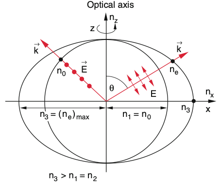
Fig.:
If we select now a specific direction of propagation for the light with the direction of
Therefore the extra-ordinary refractive index is valid for the p-polarization and the ordinary refractive index is valid for the s-polarization.
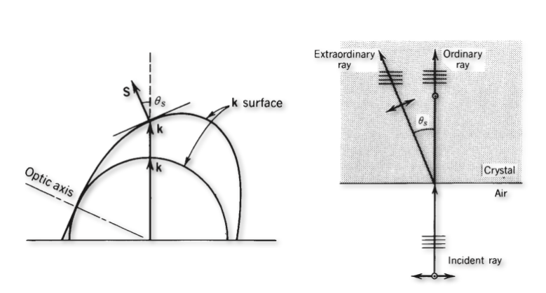
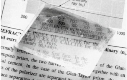
Fig.: Birefringence.
Let’s discuss the sketches above, which show the general case of birefringence. The image on the left side shows an interface between air on the bottom and the anisotropic material on the top. The wavevector is incident from below and is normal zo the surface. Its direction will intersect both k-surfaces and thereby select the ordinary refractive index and the extra-ordinary refractive index for the two different polarization directions. Both waves propgate in the same direction, so their wavefronts are perpendicular to the k-vectors as shown in the middle sketch. Yet, the Poynting vectors go in different direction. The Poynting vector, which points in the direction of energy propagation, is always perpendicular to the k-surface, since the k-surface is an isoenergy surface (think about that for a moment). This means that the beam is split into two beams with parallel wavefronts as indicated. This phenomenon is called birefringence and separates two orthogonal polarizations into two beams as indicated.
This effect is probably best visible, when you put a birefringent material like the common calcit crystal on a newpaper or book. You will immediately see the birefringence in the double images as in the figure above to the right.
The different refractive index for both polarizations make those materials very suitable for the creating polarizing optical elements like beam splitters. A selection of different polarizing beam splitters is shown in the image below.
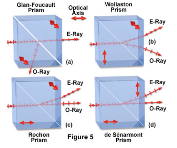
Fig.: Polarizing beam splitters.
Birefringence is often observed in mechanically stressed materials like quickly cooled glasses or stretched polymer foils. The latter is demonstrated in the images below, where we used


Fig.: Scotch tape art. Scotch tape christmas tree and tulip between crossed polarizers showing their birefringent behavior.
Wave retarders
Anisotropic materials can now but cut in specific way, for example such that the optical axis is parallel to the interface as in the picture below. Under these circumstances at normal incidence both wavevectors and both Poynting vectors of the polarizations propagate along the same direction. Yet, the p-polarization has a lower phase velocity (long k-vector) than the s-polarization. If now the incident light has now elecric field components parallel and perpedicular to the optical axis which are of same amplitude, then one component of the incident polarization is delayed in its phase with respect to the other comonent.
Let
be the incident electric field of the plane wave travelling along the z-direction with
After a material of thickness
Quarter Wave Plate
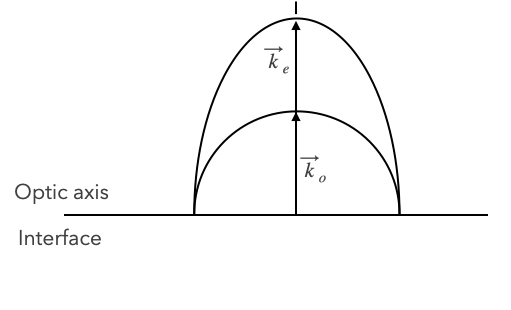
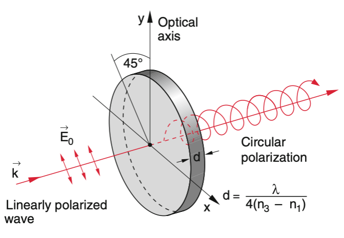
Fig.: Sketch of the conditions for a wave retarder.
If we design now a material of a certain thickness such that the phase shift is
The crystal thickness is, however, not restricted to this minimal thickness, but to any thickness which creates a phase difference of
If the two elecric field components are not of equal amplitude, then a quarter wave plate will generate elliptically polarized light. Note that if you send circular polarization to a QWP, linearly polarized light will be created.
Half Wave Plate
The phase difference between the two elecric field components could also be adjusted to be half a wavelength of
Optical Activity
In addition to retarding the propagation of a particular polarization, there are materials that rotate the plane polarization for any arbitraty orientation. Such kind of materials are called opticallly active. If linear polarized light enters a layer of an optically active material, the plane of polarization is rotated about an angle
with
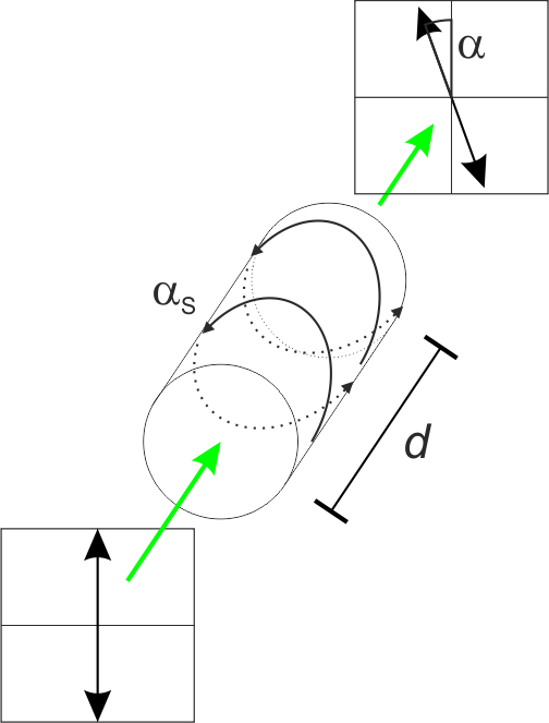
Fig.: Rotation of linearly polarized light due to an optically active medium with specific rotation
Among optically active substances one distinguishes between materials providing a positive or negative specific rotation. By definition the observer is watching against the direction of propation. If the polarization is rotated clockwise, the specific rotation is defined positive (
The physical explaination for the rotation is based on treh specific symmetry of teh optically active material. Some materials like Quartz are only active in its solid form. Thus, being optically active depends on the symmetry of teh crytsal structure. There are naturally occuring right-handed (+, d) and left-handed (-, l) Quartz crystals. In liquid or gasous phase, however, optical activity of vanishs. Other substances like sucrose or fructose are optically active in solution. Therfore, the symmetry of those molecules gives rise to the rotation of he polarization.
Without in-depth quantum mechaniscs, this phenomenon can be explained only qualitatively. Analogously to vibrations of electrons in homogenous media induced through the electric field of linear polarized waves, here one assumes an spiral motion of electrons along the direction of propagation. Indeed, the crystal structure of Quartz suggest such kind of concept, due to a spiral-like arrangment of oxygen and silicon atoms. A right-handed spiral for right-handed d-Quartz and a left-handed spiral
for l-Quartz. Structures which exists in two mirrored forms are called chiral (Greek:
If one models a linear polarized wave as a superpostion of two circular polarized waves with opposite directions of rotation
The rotary power is then defined per uni length
In liquids, however, molecules are randomly oriented. In the case of an emerging electromagnetic wave, molecules are slightly oriented causing optical activity. If
The correlation between left- and right-handed propgation and molecular struture is exploited for the spectroscopic technique of Circular Dichroism. The degree of rotation
Faraday Effect
If a linear polarized wave propagates within an magneto-optical material parallel or antiparallel to the magnetic field, polarization of the wave experiences a rotation. The reason for this effect lies in imaginary off-diaginal elements of the permativity tensor
which allows for reformulating the dielectric displacement
and
This effect is a non-local effect. The relation
Most interesting, rotation due to the Faraday effect has to be distinguished from rotation in optically active media. In optically active media, the rotation depends solely on the propagation direction. Thus, if one places a mirror after teh medium and let teh wave propagate reversly, the rotation vanishes. In constrast, Faraday rotation depends on the propagation of the wave relative to the magnetic flux. In the case
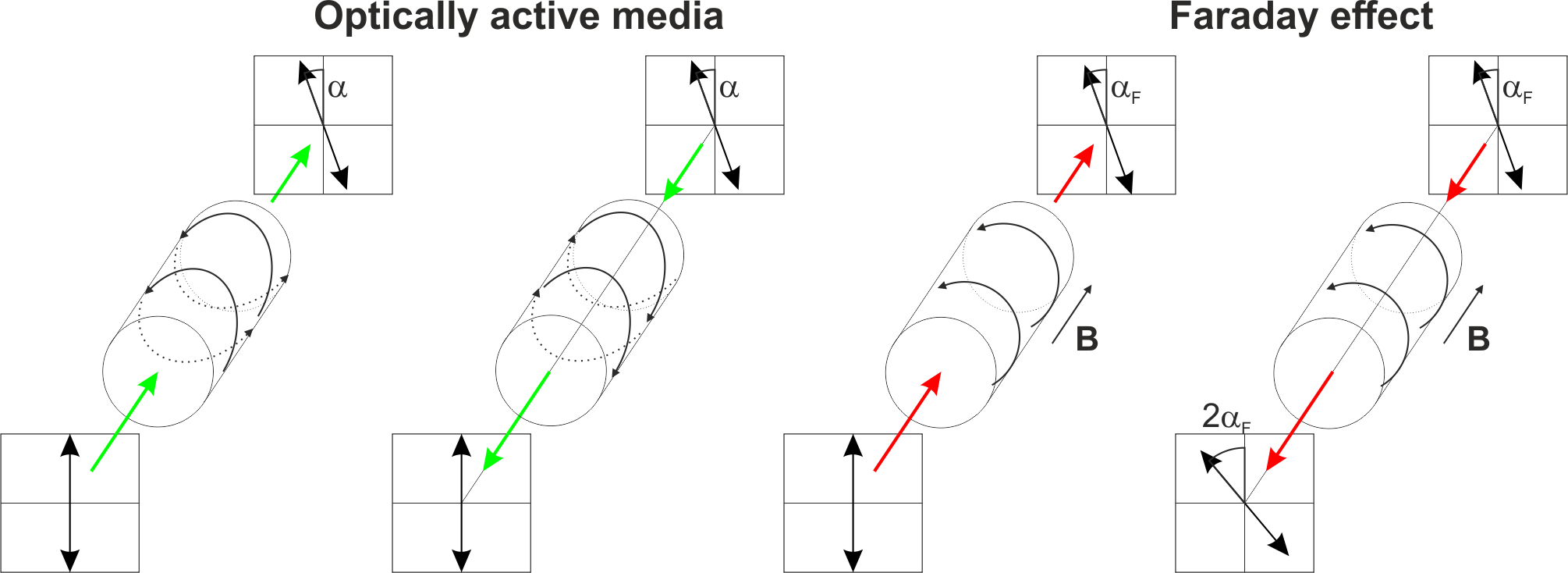
Fig.: Rotation of linearly polarized light due to an optically active medium (left) and counteracting rotation during backward propagation if the wave is reflected.(second from left). The resulting rotation, then, is
[ ]: